Method for preparing two-dimensional nano materials through hypergravity coupling
A two-dimensional nanomaterial and two-dimensional material technology, applied in the field of supergravity coupling to prepare two-dimensional nanomaterials, can solve the problems of high impurity content and difficult separation and removal, and achieve low-cost effects
- Summary
- Abstract
- Description
- Claims
- Application Information
AI Technical Summary
Problems solved by technology
Method used
Image

Examples
Embodiment 1
[0043] Using isopropanol aqueous solution as stripping solution, graphite as raw material, few-layer graphene material was prepared by supergravity coupling.
[0044] Among them: the specific gravity of the stripping liquid is between 0.955 and 0.956 g / ml, and it begins to freeze below -8°C, and the stripping liquid can completely wet the graphite sheet.
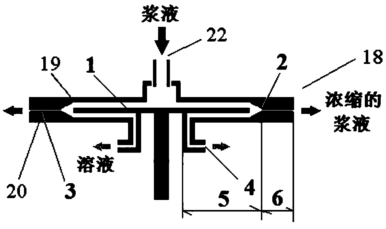
[0045] This embodiment adopts as Figure 5 The shown high-gravity coupled device for preparing two-dimensional nanomaterials is realized. The device includes a cooling cycle system composed of a refrigeration cycle pump 7 and a tube-and-tube heat exchanger 8, a high-gravity cycle stripping system, and a high-gravity cycle concentration system. Gravity circulation stripping system comprises the hypergravity coupling machine I 11 that communicates with the first metering tank 10, the first magnetic pump 9 and the cooling circulation system through pipelines; The second magnetic pump 14 is connected to the supergravity couplin...
Embodiment 2
[0061] During the preparation of graphene, the highest supergravity field levels for one rotation of the separation units of the hypergravity coupling machines I and II are still 3170 g and 4733 g, respectively. The difference between Embodiment 2 and Embodiment 1 is that the flow section of the secondary rotating flow channel in the supergravity coupling machine I is a circle with a diameter of 2 mm, and the radial length is 120 mm. The secondary rotating flow channel in the high gravity coupling machine I The radial dimension of is 1.5 times the radial dimension of the secondary rotating flow channel in the supergravity coupling machine II. The flow ratio of graphite concentrated slurry and low-concentration graphene solution is controlled at 0.5:1; the axial average linear velocity of graphite concentrated slurry reaches 65 m / s. During the stripping process, the temperature was controlled at -4°C; during the concentration process, the temperature was controlled at 1°C. In ...
Embodiment 3
[0063] During the preparation of graphene, the highest supergravity field levels for one rotation of the separation units of the supergravity coupling machine I and II are still 3170 g and 4733 g, respectively. The difference between embodiment 3 and embodiment 1 is: the flow section of the secondary rotating flow channel in the supergravity coupling machine I is a circle with a diameter of 6mm, and the radial length is 120mm, and the secondary rotating flow channel in the high gravity coupling machine I The radial dimension is twice the radial dimension of the secondary rotating flow channel in the supergravity coupling machine II; the flow ratio of the graphite thick slurry and the low-concentration graphene solution is controlled at 2:1; the axial average of the graphene slurry The line speed is 65 m / s. During the stripping process, the temperature was controlled at -3°C; during the concentration process, the temperature was controlled at 2°C. In step (1), the concentratio...
PUM
| Property | Measurement | Unit |
|---|---|---|
| Thickness | aaaaa | aaaaa |
| Thickness | aaaaa | aaaaa |
| Size | aaaaa | aaaaa |
Abstract
Description
Claims
Application Information