
Disc type labyrinth valve caged structure brazing method

A brazing method and butterfly technology, applied in welding equipment, metal processing equipment, manufacturing tools, etc., can solve the problem of poor brazing performance between solder and butterfly base material, inability to strictly seal the butterfly, and curved surface of the butterfly, etc. problem, to achieve the effect of increasing the types of brazing, reducing deformation and reducing thermal stress

Active Publication Date: 2019-08-30
WUZHONG INSTR +1
View PDF11 Cites 0 Cited by
  • Summary
  • Abstract
  • Description
  • Claims
  • Application Information

AI Technical Summary

Problems solved by technology

[0006] At present, there are many problems in the cage structure made by the above-mentioned ordinary smearing and brazing process, which are described as follows: firstly, the paint applied on the disc will easily flow into the flow channel due to the siphon phenomenon during the high-temperature sintering process. Finally, part of the flow channel openings are blocked. If more than a certain number of flow channel openings are blocked or partially blocked, the product will be scrapped.
Another situation is that the brazing performance of the solder and the base material of the disc is not good, which causes the part of the welded area to be unreliable, or even completely disengaged.
Another situation is to increase the sintering temperature in order to enhance the reliable performance of welding. Because the process temperature is too high, in this case, during the vacuum sintering process, due to the many symmetrical flow channels in the middle of the butterfly, and the thin sheet shape of the butterfly itself Due to the influence of temperature, a large thermal stress is generated, and finally the surface of the butterfly is bent, so that the butterfly cannot be strictly sealed and the product is unqualified

Method used


Image

  • Disc type labyrinth valve caged structure brazing method
  • Disc type labyrinth valve caged structure brazing method

Examples


Embodiment Construction

[0018] The present invention will now be described in further detail with reference to the drawings.

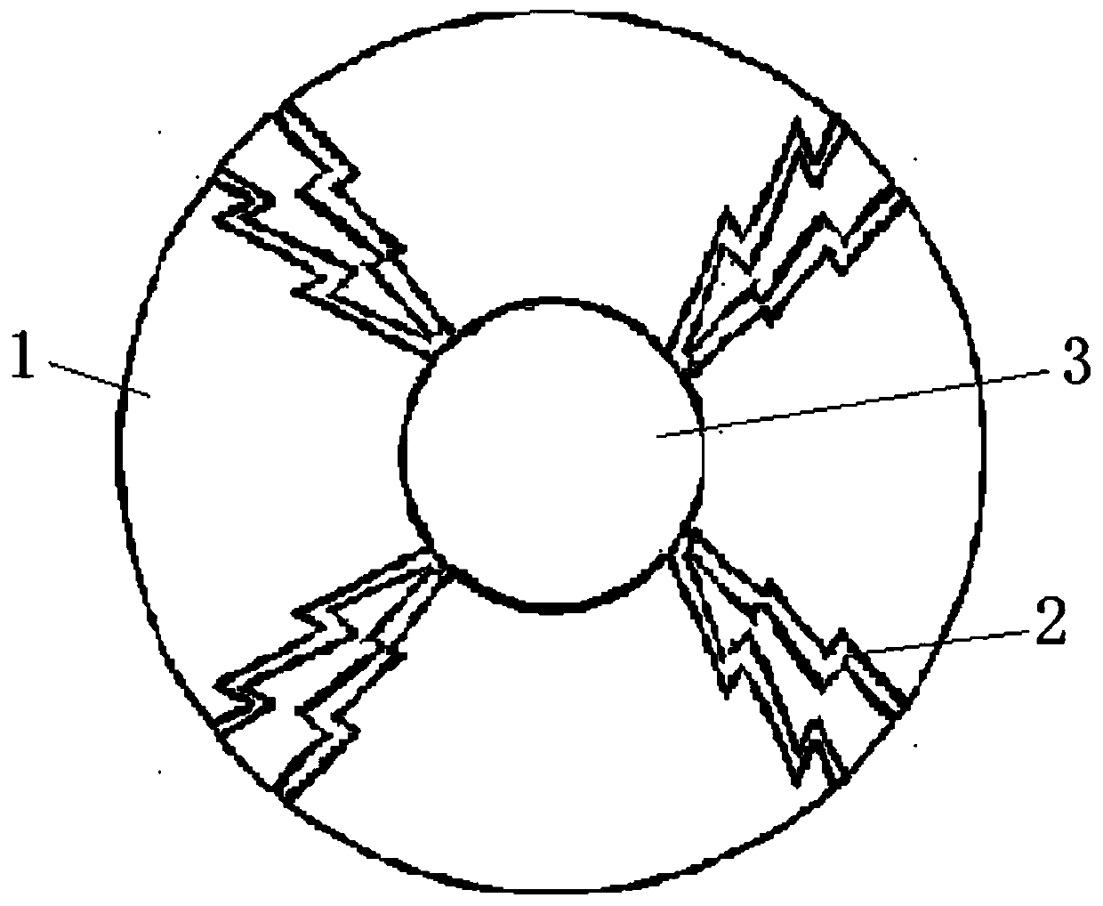
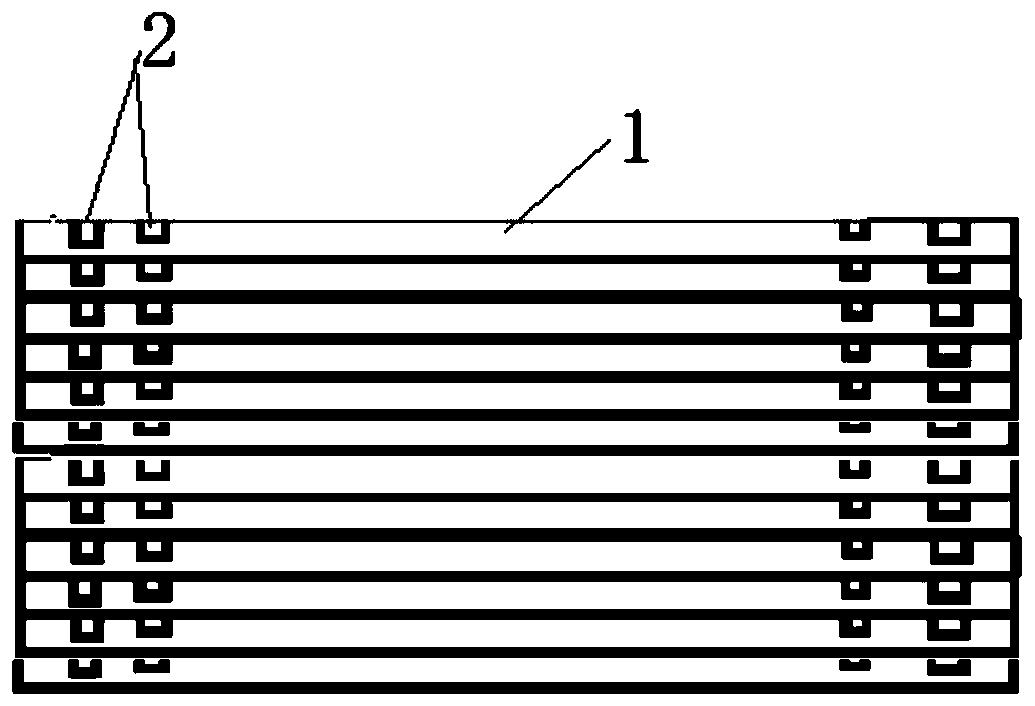
[0019] Firstly, the disc substrate 1 (the disc base material is generally 316 stainless steel, or other alloy steel, 316 stainless steel is used in this embodiment), which helps increase the welding surface area. Next, electroless nickel plating is performed on the surface of the butterfly substrate 1 with a thickness of 10 microns. For electroless nickel plating, choose low-phosphorus nickel plating as much as possible. On the one hand, the surface hardness will be reduced, and secondly, the purity of the nickel surface will be high, which helps the solder's wettability. Electroless nickel plating can improve the wettability of the butterfly substrate 1 and the solder, which can make the brazing area intact and increase the adhesion. Moreover, a variety of solders, mainly silver and copper solders, are modified with nickel on the surface It has a better brazing effect. At the ...


PUM

PropertyMeasurementUnit
thicknessaaaaaaaaaa
thicknessaaaaaaaaaa
thicknessaaaaaaaaaa

Abstract

The invention discloses a disc type labyrinth valve caged structure brazing method which comprises the following steps: step 1, carrying out sand blasting on a disc base, then carrying out chemical nickel-plating, coating the position of a runner on the disc with a nanometer and inorganic high-temperature resistant coating, after solidification, filling the runner with epoxy resin organic fillingand / or paraffin filling, and screeding to be aligned with the disc base, after solidification, coating the surface of the epoxy resin organic filling with the nanometer and inorganic high-temperatureresistant coating, and finally, coating the non-runner region of the disc base with a brazing material, so as to obtain a pre-sintering disc base; and step 2, aligning the layers of pre-sintering discbase, and then building the layers up together, so as to form a caged structure, then using a clamp for tightening, and then carrying out sintering. According to the invention, through the arrangement on the brazing process, the sintering temperature is lowered, the bonding force between welding parts is enhanced, and the port of the runner is effectively prevented from being blocked.

Description

Technical field [0001] The invention belongs to the technical field of valves, and specifically relates to a method for brazing a butterfly blade type labyrinth valve cage mounting structure. Background technique [0002] The multi-stage labyrinth pressure-reducing valve adopts a labyrinth flow control valve composed of multiple discs. Through the position of the valve core and disc assembly, the flow of the medium flowing through the valve is adjusted, and the flow of the medium through the disc Its frequent bending increases the resistance along the way and greatly reduces the pressure of high-pressure gas or steam. Due to the effective multi-stage pressure reduction, the liquid will not produce cavitation, and the noise during the pressure reduction process is reduced. [0003] The labyrinth control valve is mainly composed of multiple discs. On the surface of each disc, there are many axisymmetrically arranged small flow passages. These flow passages diverge from the central ho...

Claims


Application Information

Patent Timeline
Patent Type & Authority Applications(China)
IPC IPC(8): B23K1/00B23K1/20
CPCB23K1/0008B23K1/20
Inventor 马玉山刘海波常占东何涛刘艳玲马军
Owner WUZHONG INSTR
Learn More