Body bending rigidity measurement system and method
A bending stiffness and measurement system technology, applied in the field of body bending stiffness measurement system, can solve the problems of large volume of restraint device and servo loading device, inability to measure continuous measurement points of the body, limited bending deformation data, etc., to achieve accurate and reliable measurement results, Streamlined structure and simple structure
- Summary
- Abstract
- Description
- Claims
- Application Information
AI Technical Summary
Problems solved by technology
Method used
Image
Examples
Embodiment 1
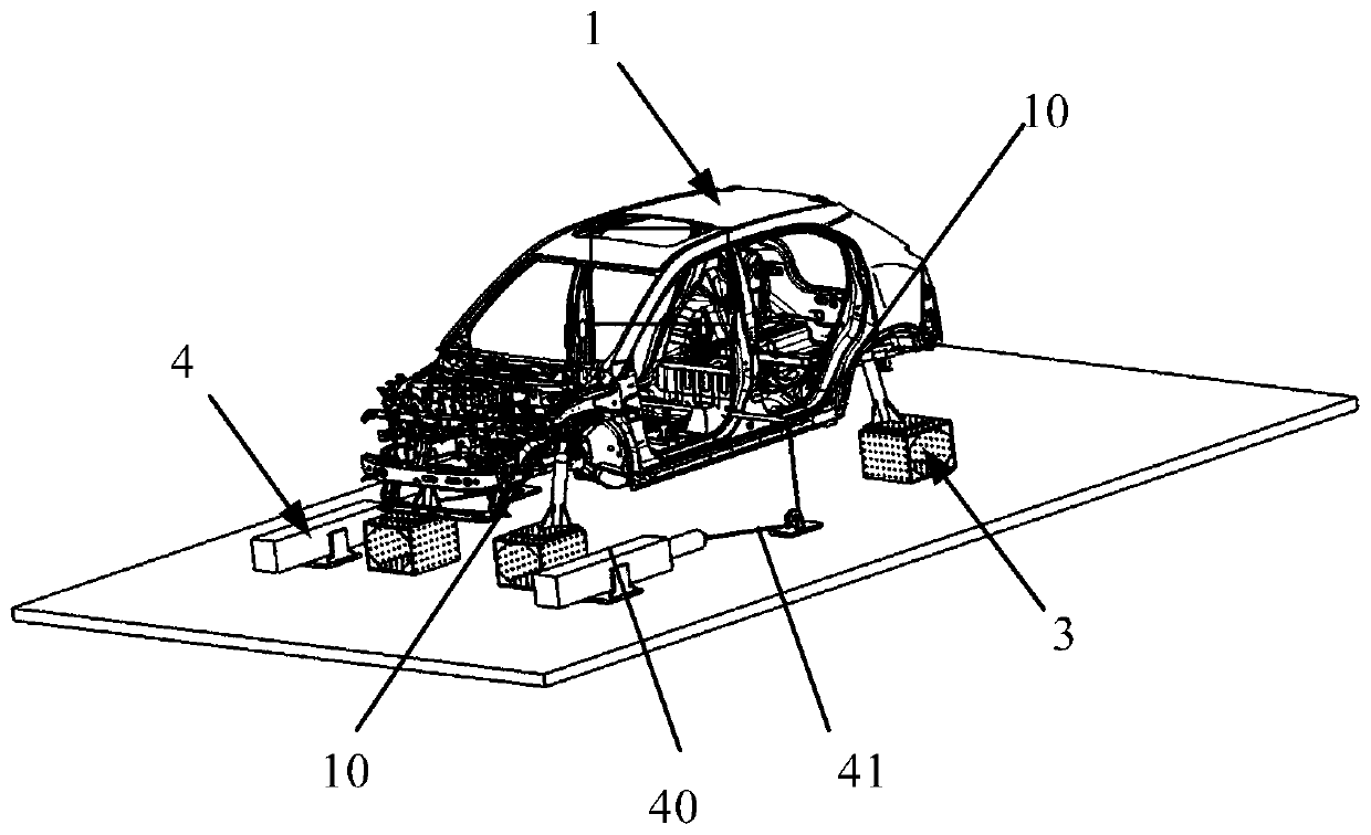
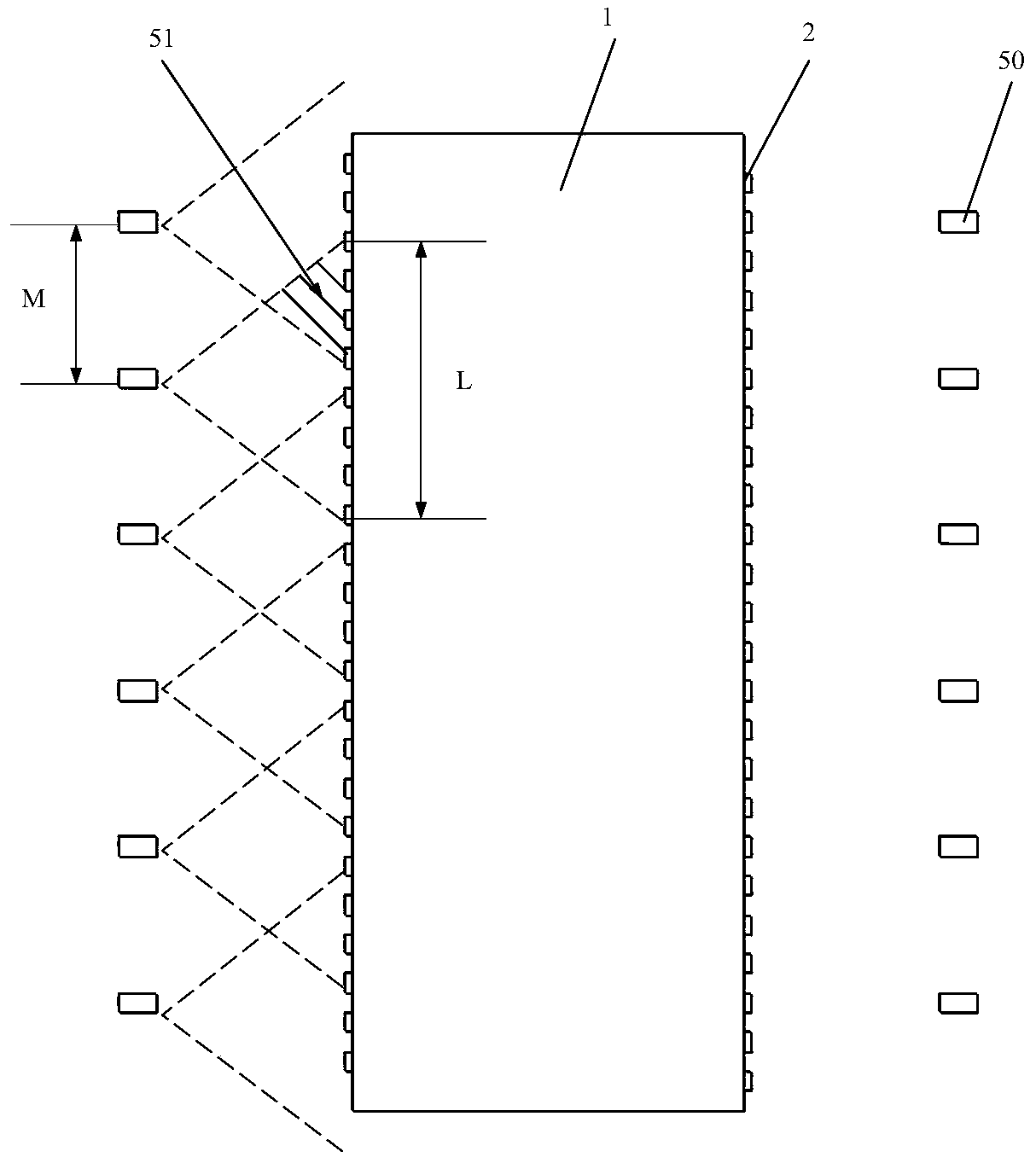
[0038] see Figure 1-3 As shown, the embodiment of the present invention provides a vehicle body bending stiffness measurement system, which includes a body-in-white 1, a body support device 3, a load loading device 4 and a camera group 5, wherein the body-in-white 1 refers to the body-in-white before welding but not painted The body is used as the detection object of the body bending stiffness measurement test. At least one side of the body in white 1 in Embodiment 1 of the present invention is provided with a plurality of measuring points 2 arranged along the horizontal direction, wherein the number and positions of the measuring points 2 are simulated by CAE It is obtained that there are more than a dozen to dozens of measuring points 2 on the body-in-white 1. In the bending stiffness measurement test, the body-in-white 1 is first firmly fixed on the steel platform through the body support device 3. The body in the embodiment 1 of the present invention The support device 3 ...
Embodiment 2
[0047] Its basic content is the same as embodiment 1, and the difference is:
[0048] The system of Embodiment 2 of the present invention also includes a computer, which is connected to all optical cameras 50, and is used to calculate the bending stiffness of the vehicle body using a preset algorithm according to the relative position difference, ie displacement, of the measuring point 2 in the vertical direction before and after applying a predetermined load.
[0049] The default algorithm is:
[0050] k=F / x
[0051] Among them, k is the bending stiffness of the vehicle body; F is the predetermined load; x is the relative position difference in the vertical direction of the measuring point.
[0052] It should be noted that the calculation process can be performed by computer or by other means. In order to improve the calculation effect in Embodiment 2 of the present invention, it is preferable to use a computer for calculation.
Embodiment 3
[0054] Its basic content is the same as embodiment 1, and the difference is:
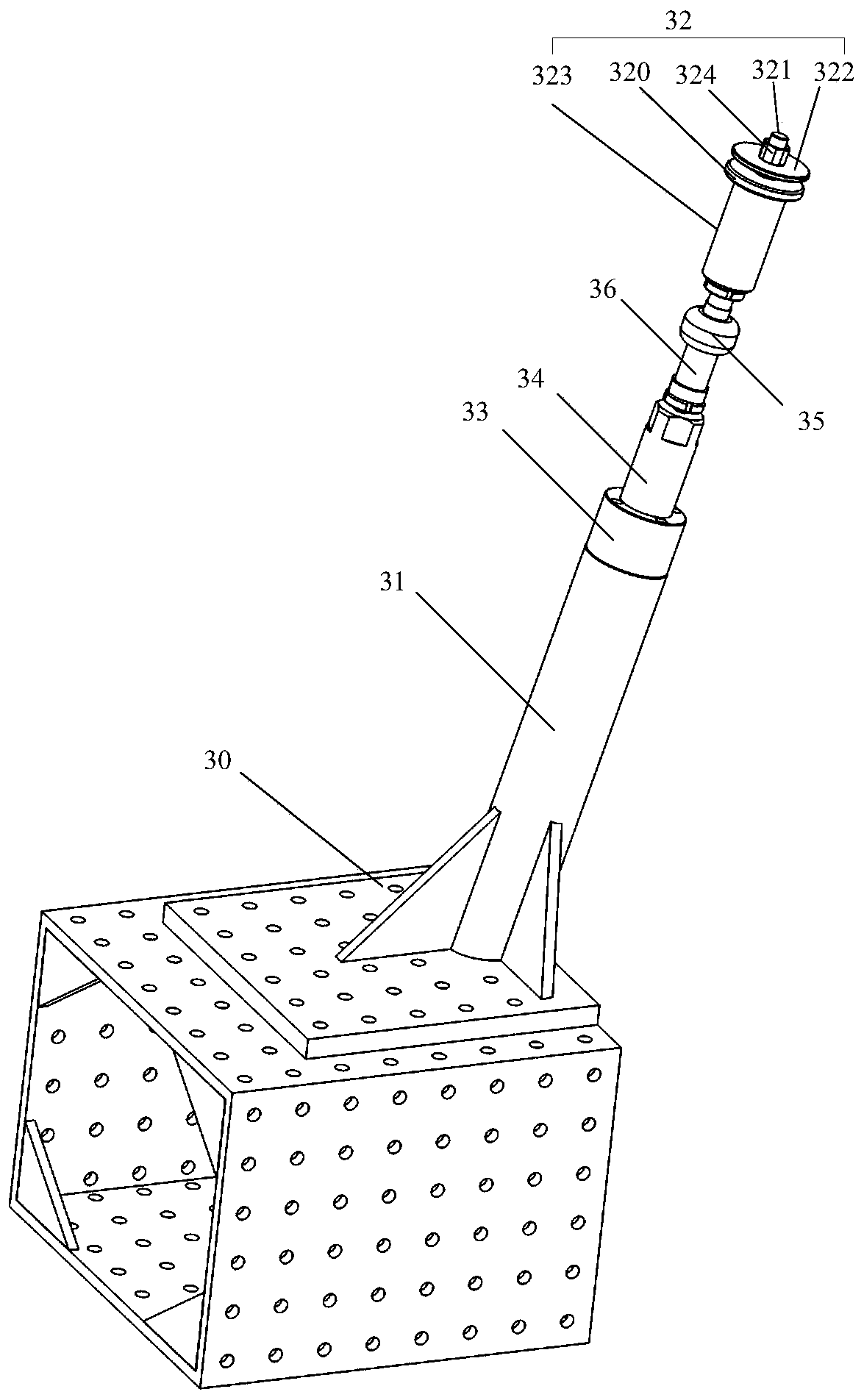
[0055] see image 3 As shown, the vehicle body supporting device 3 also includes a height adjustment screw 33, a sleeve 34, a ball joint 35 and a universal joint connecting sleeve 36, and the universal joint connecting sleeve 36 is connected to the bottom of the ball joint 35. end, the height adjustment screw 33 is connected with the suspension mount 32 through a ball-and-socket universal joint 35, so that the suspension mount 32 has a swing margin at a certain angle to adapt to different vehicle models and test requirements, while the suspension mount 32 It has different length specifications to meet the requirements of different vehicle models and test requirements for support height and swing allowance.
[0056] Wherein the suspension mounting part 32 is used for carrying out stable connection and fixing with the vehicle body, and its top structure is similar to the actual suspension assembly in...
PUM
 Abstract
Description
Claims
Application Information
 - R&D
- Intellectual Property
- Life Sciences
- Materials
- Tech Scout
- Unparalleled Data Quality
- Higher Quality Content
- 60% Fewer Hallucinations
Browse by: Latest US Patents, China's latest patents, Technical Efficacy Thesaurus, Application Domain, Technology Topic, Popular Technical Reports.
© 2025 PatSnap. All rights reserved.Legal|Privacy policy|Modern Slavery Act Transparency Statement|Sitemap|About US| Contact US: help@patsnap.com


