Microfluidic sample concentration device and method of use based on photothermal evaporation
A concentrating device and microfluidic technology, applied in the field of microfluidics, can solve the problems of difficult gas-liquid evaporation area, reduced evaporation efficiency, low evaporation system efficiency, etc., to increase evaporation area, improve efficiency, and solve the problem of free gas-liquid interface. uncontrollable effects
- Summary
- Abstract
- Description
- Claims
- Application Information
AI Technical Summary
Problems solved by technology
Method used
Image
Examples
Embodiment 1
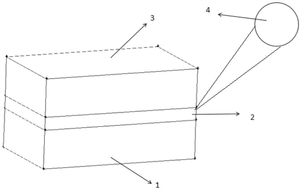
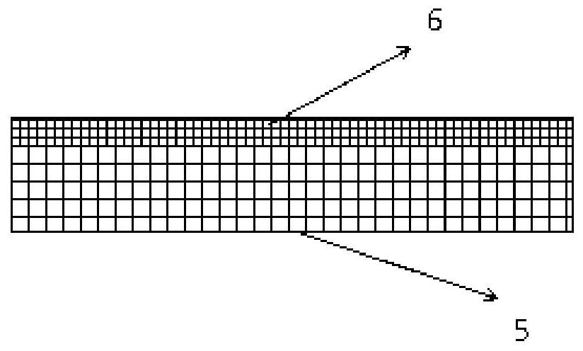
[0022] Embodiment 1: see figure 1 with figure 2, a microfluidic sample concentration device based on photothermal evaporation, comprising a sample solution channel 1, that is, a substrate, a porous photothermal evaporation layer 2 is arranged above the sample solution channel 1, and a porous photothermal evaporation layer 2 is arranged above the porous photothermal evaporation layer 2 A carrier gas channel 3 is provided, and a light source 4 is provided on the outside of the porous photothermal evaporation layer 2; the porous photothermal evaporation layer 2 is composed of a hydrophilic porous photothermal medium layer 5 and a hydrophobic gas diffusion layer 6; the hydrophilic The water porous photothermal medium layer 5 generates capillary suction force on the liquid, so that the sample solution enters the hydrophilic porous photothermal medium layer 5. At the same time, the hydrophilic porous photothermal medium layer 5 absorbs the incident light of the light source 4 to ge...
Embodiment 2
[0028] Embodiment 2. The method of using a microfluidic sample concentration device based on photothermal evaporation, the concentration device includes a sample solution channel 1, a porous photothermal evaporation layer 2 is arranged above the sample solution channel 1, and the porous photothermal evaporation layer 2 is arranged above the sample solution channel 1. A carrier gas channel 3 is arranged above the evaporation layer 2, and a light source 4 is arranged outside the porous photothermal evaporation layer 2; the porous photothermal evaporation layer 2 is composed of a hydrophilic porous photothermal medium layer 5 and a hydrophobic gas diffusion layer 6 Composition; the hydrophobic gas diffusion layer 6 is a hydrophobic structure, located on the upper part of the hydrophilic porous photothermal medium layer 5; the carrier gas channel 3 has a gas microchannel structure, and the inlet of the gas microchannel is connected to the outlet of the purge gas storage device The ...
Embodiment 3
[0033] Embodiment 3: A microfluidic sample concentration device based on photothermal evaporation can be prepared as follows:
[0034] A. Processing of sample solution channel 1 and carrier gas channel 3: select two pieces of polydimethylsiloxane, rubber or resin elastic materials with the same shape and size as the matrix of sample solution channel 1 and carrier gas channel 3 respectively, through The soft lithography technique processes solution channels and gas microchannels on the substrate, respectively.
[0035] B, the making of porous photothermal evaporation layer 2:
[0036] B1. Evenly mix liquid phenol, calcium lignosulfonate, and sodium hydroxide at a mass ratio of 39.2:4.4:1, heat at a constant temperature of 80°C for 30 minutes, and then add 30% based on the mass ratio of 1:1.27 based on the mass of the mixture Formaldehyde aqueous solution was vacuum dehydrated at a temperature of 50° C. and a pressure of 0.1 MPa for 30 minutes to obtain a water-based phenolic r...
PUM
 Abstract
Description
Claims
Application Information
 - R&D
- Intellectual Property
- Life Sciences
- Materials
- Tech Scout
- Unparalleled Data Quality
- Higher Quality Content
- 60% Fewer Hallucinations
Browse by: Latest US Patents, China's latest patents, Technical Efficacy Thesaurus, Application Domain, Technology Topic, Popular Technical Reports.
© 2025 PatSnap. All rights reserved.Legal|Privacy policy|Modern Slavery Act Transparency Statement|Sitemap|About US| Contact US: help@patsnap.com


