Bonding wire cathode passivation protecting treatment technology

A technology of protection treatment and bonding wire, which is applied in the field of cathodic passivation protection of bonding wires, can solve the problems of silver bonding wires such as reduced conductivity, reduced light reflection, and large surface roughness, without affecting the surface shape. Good appearance and appearance, maintain brightness, and good anti-corrosion effect

Inactive Publication Date: 2019-09-10
广东禾木科技有限公司
View PDF11 Cites 3 Cited by
  • Summary
  • Abstract
  • Description
  • Claims
  • Application Information

AI Technical Summary

Problems solved by technology

However, high-silver-content bonding wires are prone to silver ion migration under wet conditions, and are easily corroded by sulfides and oxygen in the air to discolor the surface, which seriously affects the reflectance, long-term reliability and service life of the silver wire.
[0004] At present, the main methods commonly used at home and abroad to prevent the discoloration of silver bonding wires are: plating precious metals on the surface of silver bonding wires, bright silver plating, chemical passivation with chromic acid, and dip-coating organic anti-silver discoloration agents. The final silver bonding wire will not only reduce the conductivity, but also reduce the reflectivity, and the reaction rate can be reduced by 5-15%, which greatly affects the use of silver wire.
At the same time, the chromic acid chemical passivation method currently on the market uses hexavalent chromium, which has a huge impact on the environment, and the waste liquid treatment is inconvenient, and the chemical passivation method still has a large surface roughness after passivation. Technical defects such as affecting surface brightness

Method used


Image

  • Bonding wire cathode passivation protecting treatment technology
  • Bonding wire cathode passivation protecting treatment technology
  • Bonding wire cathode passivation protecting treatment technology

Examples


Embodiment 1

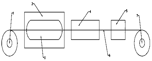
[0026] see figure 1 , in Embodiment 1 of the present invention, a cathodic passivation protection treatment process for bonding wires, comprising the following steps: drawing the bonding wire raw material core as a raw wire, and annealing the drawn bonding wire precursor 6 1. Use trivalent chromium cathode passivation solution to passivate the bonded wire precursor 6 after annealing, and use deionized water in the cleaning box 4 for the bonded wire precursor 6 passivated by trivalent chromium cathode passivation solution Cleaning, drying the cleaned bonding wire precursor 6 in the drying box 5 and rewinding and packaging the dried bonding wire precursor 6 through the take-up wheel 7 .

[0027] Further, the specific implementation method of drawing the raw material core of the bonding wire is: rough drawing and fine drawing of the raw material core of the bonding wire with a diameter of 2000 μm to 2500 μm, and draw it to a diameter of 25 μm.

[0028] Further, the specific impl...

Embodiment 2

[0032] see figure 1 , in embodiment 2 of the present invention, a kind of cathodic passivation protection treatment process of bonding wire, it comprises the following steps: carry out raw wire drawing to bonding wire raw material core, anneal to the bonded wire raw wire 6 after drawing 1. Use trivalent chromium cathode passivation solution to passivate the bonded wire precursor 6 after annealing, and use deionized water in the cleaning box 4 for the bonded wire precursor 6 passivated by trivalent chromium cathode passivation solution Cleaning, drying the cleaned bonded wire precursor 6 in the drying box 5 and rewinding and packaging the dried bonded wire precursor 6 through the take-up wheel 7 .

[0033] Further, the specific implementation method of drawing the raw material core of the bonding wire is: rough drawing and fine drawing of the raw material core of the bonding wire with a diameter of 2000 μm to 2500 μm, and draw it to a diameter of 25 μm.

[0034] Further, the s...

Embodiment 3

[0038] see figure 1, in embodiment 3 of the present invention, a kind of cathodic passivation protection treatment process of bonding wire, it comprises the following steps: carry out raw wire drawing to bonding wire raw material core, carry out annealing to the bonded wire raw wire 6 after drawing 1. Use trivalent chromium cathode passivation solution to passivate the bonded wire precursor 6 after annealing, and use deionized water in the cleaning box 4 for the bonded wire precursor 6 passivated by trivalent chromium cathode passivation solution Cleaning, drying the cleaned bonding wire precursor 6 in the drying box 5 and rewinding and packaging the dried bonding wire precursor 6 through the take-up wheel 7 .

[0039] Further, the specific implementation method of drawing the raw material core of the bonding wire is: rough drawing and fine drawing of the raw material core of the bonding wire with a diameter of 2000 μm to 2500 μm, and draw it to a diameter of 20 μm.

[0040] ...


PUM

PropertyMeasurementUnit
diameteraaaaaaaaaa
diameteraaaaaaaaaa

Abstract

The invention relates to the technical field of bonding wire production, and particularly discloses a bonding wire cathode passivation protecting treatment technology. The bonding wire cathode passivation protecting treatment technology comprises the following steps that raw wire drawing is performed on a bonding wire raw material core, annealing is performed on the bonding wire raw wire obtainedafter drawing, passivation is performed on the bonding wire raw wire obtained after annealing through a trivalent chromium cathode passivation solution, the bonding wire raw wire obtained after passivation of the trivalent chromium cathode passivation solution is washed with deionized water inside a cleaning box, the cleaned bonding wire raw wire is dried inside a drying box, and the dried bondingwire raw wire is rewound and packaged through a take-up wheel; the bonding wire cathode passivation protecting treatment technology can provide a flat passivation layer, under control of additional current, a layer of stable and smooth nanoscale solid phase membrane is formed and covers the surface of a metal substrate through electrochemical transition.

Description

technical field [0001] The invention relates to the technical field of bonding wire production, in particular to a bonding wire cathodic passivation protection treatment process. Background technique [0002] Driven by the trend of high density, high integration and miniaturization, semiconductor components widely used in military products, smart phones and unmanned vehicles have higher and higher requirements for packaging technology, materials and product quality. Bonding technology needs to adapt to increasingly stringent conditions such as narrow pitches and long distances. As one of the four key basic materials in the field of microelectronic packaging, bonding wire is the inner lead for realizing the electrical interconnection between the chip and the lead frame. More than 80% of the interconnection of microelectronic components adopts wire bonding technology. The quality of bonding wire directly determines the performance of IC packaging products. [0003] As a prec...

Claims


Application Information

Patent Timeline
Patent Type & Authority Applications(China)
IPC IPC(8): C25D9/08C25D7/06C25D5/34C22F1/14C22F1/02
CPCC22F1/02C22F1/14C25D5/34C25D7/0607C25D9/08
Inventor 杨斌崔成强周章桥张昱杨冠南
Owner 广东禾木科技有限公司
Why Eureka
Try Eureka