Secondary side synchronous rectification controller circuit capable of adaptively driving voltage regulation period by period

A driving voltage and synchronous rectification technology, which is applied in control/regulation systems, high-efficiency power electronic conversion, instruments, etc., can solve the problem of not being applicable to other types of primary-side controller architectures, poor user experience, and inability to apply to primary-side controllers And other issues

Pending Publication Date: 2019-09-10
江苏芯潭微电子有限公司
View PDF0 Cites 5 Cited by
  • Summary
  • Abstract
  • Description
  • Claims
  • Application Information

AI Technical Summary

Problems solved by technology

[0003] The existing synchronous rectification circuit can only match one or several primary-side controller architectures, and there are several ways: The first is to use a zero-current comparator to realize DCM and QR mode synchronous rectification. The working block diagram is as follows: figure 1 As shown, the zero-current comparator directly samples the voltage across the MOS tube, and when the voltage on the MOS tube (equivalent to the loop current) gradually decreases to about -15mV, the MOS tube is turned off, which is not a true zero-current comparison. The disadvantage is that it can only be used in the two flyback structures of DCM and QR, and cannot be applied to the primary side controller with CCM working mode; the second is to use the area method to realize DCM synchronous rectification, and the working block diagram is as follows figure 2 As shown, the disadvantage of this method is that it can only work in the controller architecture of DCM mode, and cannot be applied to other types of primary-side controller architectures. Due to the reason of the primary-side DCM controller architecture, it can only meet the needs of those whose output power is less than 15W. At the same time, the application require

Method used


Image

  • Secondary side synchronous rectification controller circuit capable of adaptively driving voltage regulation period by period
  • Secondary side synchronous rectification controller circuit capable of adaptively driving voltage regulation period by period
  • Secondary side synchronous rectification controller circuit capable of adaptively driving voltage regulation period by period

Examples


Embodiment Construction

[0018] In order to further illustrate a secondary side synchronous rectification controller circuit with cycle-by-cycle self-adaptive driving voltage adjustment of the present invention, the technical means adopted to achieve the intended purpose of the invention and the effects achieved, the following will be combined with the accompanying drawings and preferred embodiments , a detailed description will be given of the specific implementation, structure, features and efficacy of the secondary edge synchronous rectification controller circuit for cycle-by-cycle adaptive drive voltage adjustment proposed by the present invention.

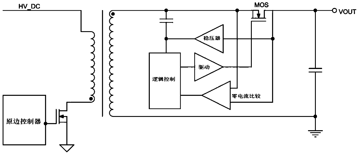
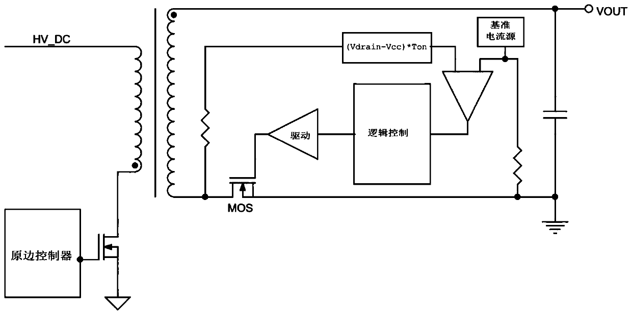
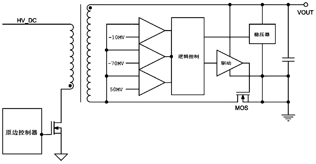
[0019] Please refer to Figure 1 to Figure 3 , which is a structural schematic diagram of an exemplary synchronous rectification controller circuit.

[0020] exist figure 1 Among them, in order to use the zero-current comparator to realize DCM and QR mode synchronous rectification, the zero-current comparator directly samples the voltage at both end...


PUM


Abstract

The invention discloses a secondary side synchronous rectification controller circuit capable of adaptively driving voltage regulation period by period, and the secondary side synchronous rectification controller circuit is mainly applied to a flyback switching power supply system. The time of each switch period is recorded by a period-by-period timing module; based on the average time and the change tendency of the first N periods, the opening time node of a first MOS transistor in the next period is automatically estimated, and therefore a second MOS transistor of the secondary side is accurately switched off before the first MOS transistor is started; when the current of the secondary side loop is reduced to zero or before the first MOS transistor is switched on, the amplitude of the driving voltage is reduced by an adaptive driving voltage adjustment module, and then the second MOS transistor is quickly switched off, so as to ensure that the flyback switching power supply system does not generate the risk that the primary side and the secondary side are conducted at the same time in any working mode; and meanwhile, the conversion efficiency of the system is improved to the maximum extent.

Description

technical field [0001] The invention relates to the field of AC-DC secondary side synchronous rectification circuits, in particular to a secondary side synchronous rectification controller circuit for cycle-by-cycle self-adaptive driving voltage adjustment. Background technique [0002] At present, flyback AC-DC is widely used in the field of small and medium power chargers and adapters. As the battery capacity of handheld devices increases and the complexity of electrical equipment increases, chargers and adapters with low power consumption and high power density will gradually become the mainstream, and the problem of heat dissipation has become an urgent issue to be solved. [0003] The existing synchronous rectification circuit can only match one or several primary-side controller architectures, and there are several ways: The first is to use a zero-current comparator to realize DCM and QR mode synchronous rectification. The working block diagram is as follows: figure 1...

Claims


Application Information

Patent Timeline
IPC IPC(8): H02M7/217H02M3/335
CPCH02M3/33592H02M7/217Y02B70/10
Inventor 倪惠清成祥陈照平
Owner 江苏芯潭微电子有限公司
Why Eureka
Try Eureka