Branch loading and parasitic structure-based base station antenna
A technology of parasitic structures and base station antennas, applied in antennas, resonant antennas, loop antennas, etc., can solve the problems of antenna impedance matching and radiation characteristics, high processing costs, low radiation gain, etc., to achieve mass production and antenna radiation The effect of high gain and stable radiation performance
- Summary
- Abstract
- Description
- Claims
- Application Information
AI Technical Summary
Problems solved by technology
Method used
Image
Examples
Embodiment 1
[0031] refer to figure 1 , figure 2 , image 3 , Figure 4 and Figure 5
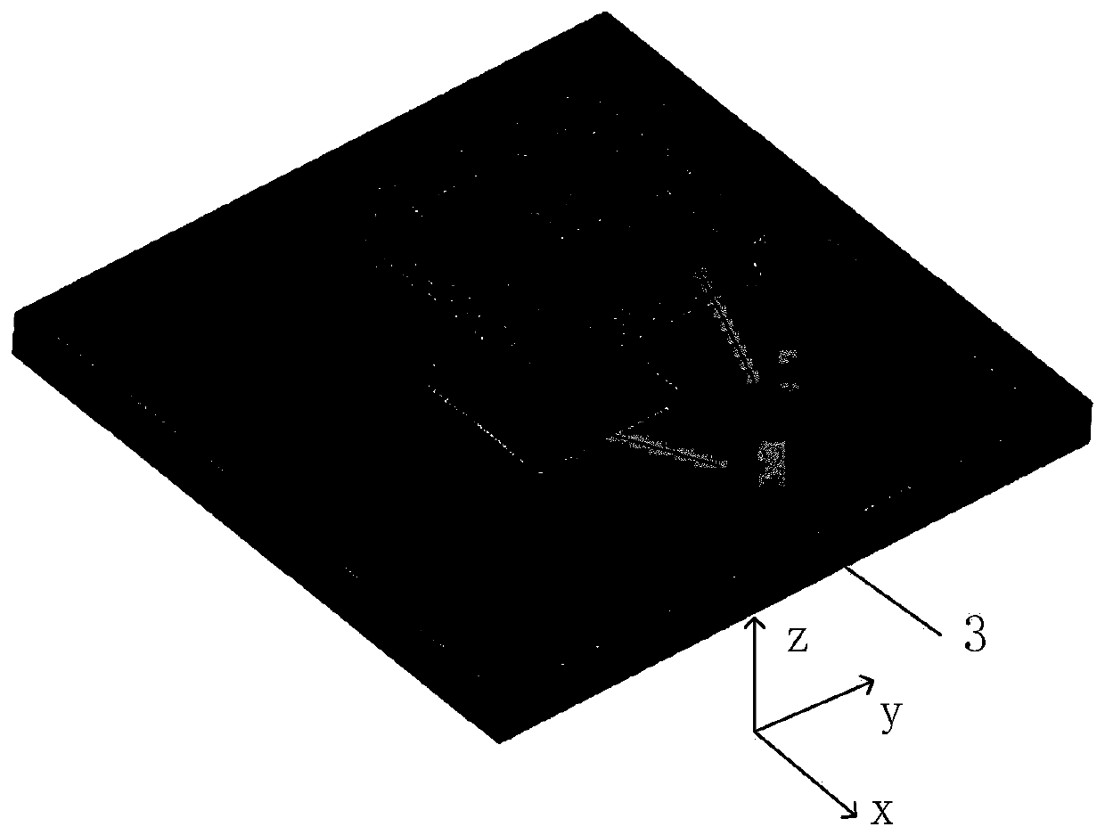
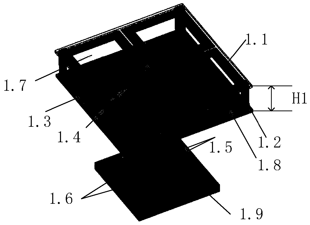
[0032] A base station antenna based on stub loading and parasitic structure loading, including a radiating structure 1, a reflector 2 and a feeding floor 3, the radiating structure 1 is composed of crossed dipoles 1.1, four identical angular metal posts 1.2, parasitic A metal ring 1.3, a microstrip feeder 1.4, a coaxial line 1.5, two identical short-circuit metal columns 1.6, a first dielectric plate 1.7, a second dielectric plate 1.8 and a third dielectric plate 1.9; the first dielectric plate 1.7 , the second dielectric plate 1.8 and the third dielectric plate 1.9 are located directly above the reflection plate; the crossed dipoles 1.1 and the feeding floor 3 are printed on the lower surfaces of the first dielectric plate 1.7 and the third dielectric plate 1.9 respectively ; The two identical short-circuit metal columns 1.6 are connected to the feeder floor 3;
[0033] The four identical angula...
Embodiment 2
[0042] The first dielectric plate 1.7, the second dielectric plate 1.8 and the third dielectric plate 1.9 are parallel to each other, and the distance between the first dielectric plate and the second dielectric plate is expressed as H1, wherein H1 is 5-20mm. H1 is 5mm.
[0043] The four identical angular metal pillars 1.2 are located at both ends of the diagonal line of the first dielectric plate 1.7, and are perpendicular to the first dielectric plate 1.7.
[0044] The length of each angular metal pillar 1.2 is expressed as L2, the height is expressed as H2, and the thickness is expressed as T1, wherein, L2 is 0.5-5mm, H2 is 5-20mm, and T1 is 0.5-3mm. L2 is 0.5mm, H2 is 5mm, and T1 is 0.5mm.
[0045] The parasitic metal ring 1.3 has a square ring structure, and the distance from the edge of the second dielectric plate is L3, wherein L3 is 0.5-5 mm. L3 is 0.5mm.
[0046] The line width of the parasitic metal ring (1.3) is expressed as W1, the width of each rectangular ring...
Embodiment 3
[0049] The first dielectric plate 1.7, the second dielectric plate 1.8 and the third dielectric plate 1.9 are parallel to each other, and the distance between the first dielectric plate and the second dielectric plate is expressed as H1, wherein H1 is 5-20 mm. H1 is 20mm.
[0050] The four identical angular metal pillars 1.2 are located at both ends of the diagonal line of the first dielectric plate 1.7, and are perpendicular to the first dielectric plate 1.7.
[0051] The length of each angular metal post (1.2) is expressed as L2, the height is expressed as H2, and the thickness is expressed as T1, wherein L2 is 0.5-5mm, H2 is 5-20mm, and T1 is 0.5-3mm. L2 is 5mm, H2 is 20mm, and T1 is 3mm.
[0052] The parasitic metal ring 1.3 has a square ring structure, and the distance from the edge of the second dielectric plate is L3, wherein L3 is 0.5-5 mm. L3 is 5mm.
[0053] The line width of the parasitic metal ring (1.3) is expressed as W1, the width of each rectangular ring is ...
PUM
 Abstract
Description
Claims
Application Information
 - R&D
- Intellectual Property
- Life Sciences
- Materials
- Tech Scout
- Unparalleled Data Quality
- Higher Quality Content
- 60% Fewer Hallucinations
Browse by: Latest US Patents, China's latest patents, Technical Efficacy Thesaurus, Application Domain, Technology Topic, Popular Technical Reports.
© 2025 PatSnap. All rights reserved.Legal|Privacy policy|Modern Slavery Act Transparency Statement|Sitemap|About US| Contact US: help@patsnap.com


