Direct current transmission fault recovery control method and system for avoiding continuous commutation failure

A technology for commutation failure and DC transmission, which is applied in the direction of AC network voltage adjustment, power transmission AC network, reactive power compensation, etc. It can solve the dynamic reactive power interaction of the AC-DC system that cannot be quantified, and DC restoration without considering the voltage distortion of the commutation bus Process impact, unable to meet the requirements of DC current limitation, etc., to improve the recovery characteristics and avoid the effect of continuous commutation failure

Active Publication Date: 2019-09-13
CHONGQING CITY MANAGEMENT COLLEGE +1
View PDF9 Cites 12 Cited by
  • Summary
  • Abstract
  • Description
  • Claims
  • Application Information

AI Technical Summary

Problems solved by technology

However, the above method cannot quantify the dynamic reactive power interaction of the AC-DC system, and the control effect is difficult to guarantee
In addition, some studies have designed a new reactive power controller to replace the low-voltage current limiting control in order to improve the DC recovery process from the perspective of improving the reactive power characteristics of the DC inverter station, but the calculation of the DC current control command value assumes a constant cut-off angle , fails to fully consider the dynamic change of the turn-off angle during the voltage drop, and completely repl

Method used


Image

  • Direct current transmission fault recovery control method and system for avoiding continuous commutation failure
  • Direct current transmission fault recovery control method and system for avoiding continuous commutation failure
  • Direct current transmission fault recovery control method and system for avoiding continuous commutation failure

Examples


Embodiment 1

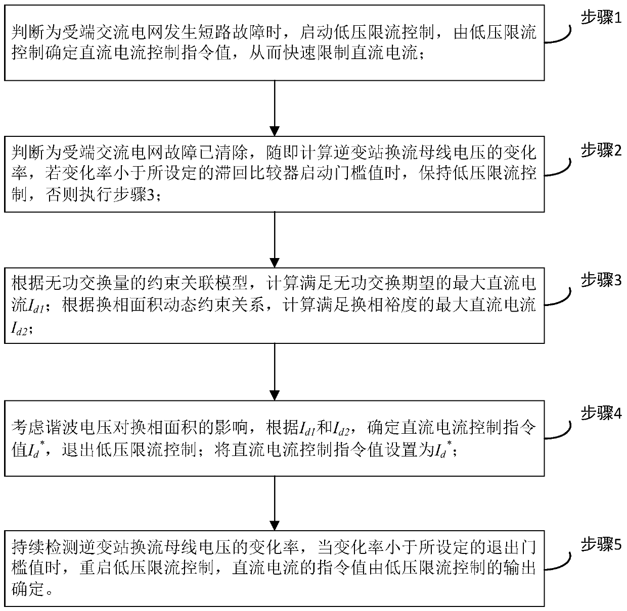
[0045] This embodiment discloses a DC transmission fault recovery control method and system to avoid continuous commutation failure, such as figure 1 As shown, the method mainly includes the following steps:

[0046] Step 1: Detect the converter bus voltage of the inverter station. When the converter bus voltage is lower than the minimum allowable operating voltage of the grid, it is judged that the receiving end AC grid has a short-circuit fault, and the low voltage current limit control is activated, and the low voltage current limit control determines the DC current Control the command value to quickly limit the DC current;

[0047] Step 2: When the converter bus voltage rises and the inverter station receives the relay protection signal, it is judged that the AC grid fault at the receiving end has been cleared, and then the rate of change of the converter bus voltage of the inverter station is calculated. The change rate of the station converter bus voltage is less than the se...

Embodiment 2

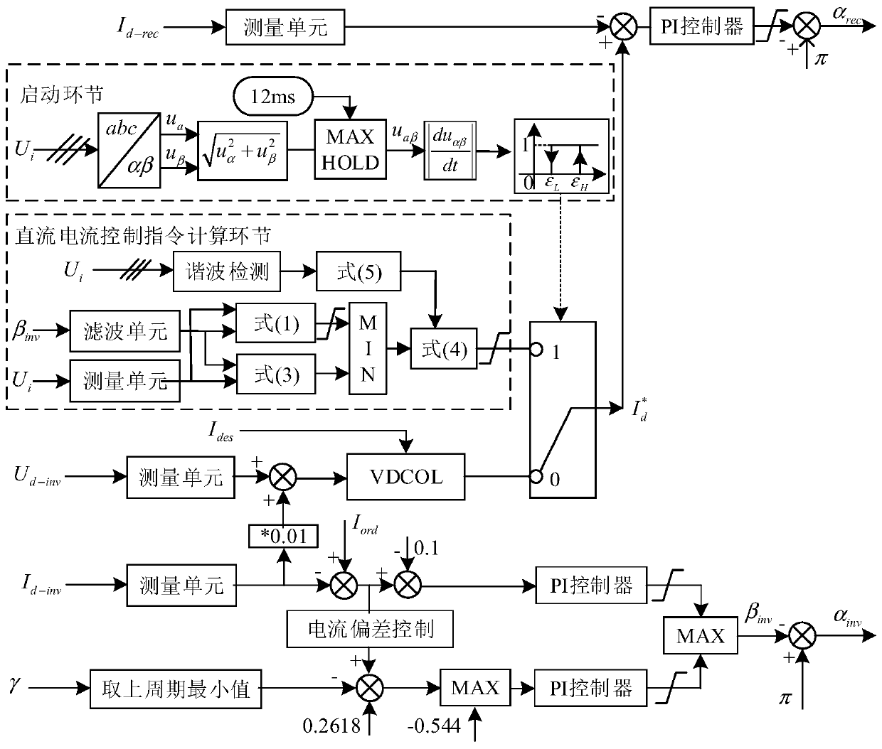
[0068] This embodiment provides a DC transmission fault recovery control and system that avoids continuous commutation failure, and the control system includes a DC current control command calculation module and a start module;

[0069] The DC current control instruction calculation module includes a first measurement unit, a filter unit, a harmonic detection unit, and a calculation unit; the first measurement unit is used to collect the converter bus voltage; the filter unit is used to collect the lead trigger angle; The harmonic detection unit is used to detect the harmonic voltage; the calculation unit is used to calculate the maximum DC current I that meets the expectation of reactive power exchange based on the data of the first measurement unit, the filter unit and the harmonic detection unit d1 , The maximum DC current I that meets the commutation margin d2 And the direct current control command value;

[0070] The start module includes a second measurement unit, a second cal...

Embodiment 3

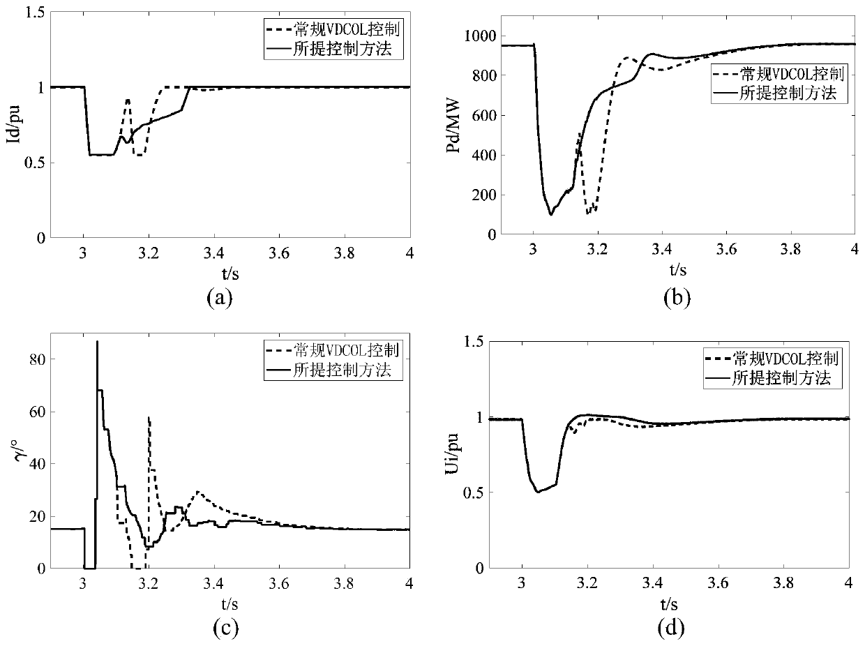
[0078] This embodiment provides a specific simulation verification example of the present invention:

[0079] The CIGRE HVDC standard test model is used to verify the fault recovery control method proposed in the present invention. The main parameters of the simulation model are as follows: the converter station adopts a 12-pulse converter, the rated DC voltage is 500kV, the rated DC current is 2kA, and the AC bus rated voltage U on the high voltage side of the converter transformer i =230kV, converter transformation ratio k=1.1, number of pole pairs N=2, equivalent short-circuit impedance X on the secondary side of the transformer c =13.32Ω, the reactive power compensation device is equivalent to accommodate B c =0.01184S, the short-circuit ratio of the AC system is 2.5. The inverter station outputs the expected value of reactive power to the receiving end AC system △Q=60Mvar. The threshold of the AC voltage change rate at which the recovery controller starts and exits is taken ...


PUM


Abstract

The invention relates to the technical field of power system protection and control, in particular to a direct current transmission fault recovery control method and system for avoiding continuous commutation failure. The method comprises the following steps of: when a short-circuit fault occurs in a receiving end alternating current power grid, starting low-voltage current-limiting control, and determining a direct current control instruction value by the low-voltage current-limiting control; when the fault of the receiving end alternating current power grid is cleared and the change rate ofa converter bus voltage of an inverter station is smaller than a set starting threshold value, according to the maximum direct current meeting reactive exchange expectation and the maximum direct current meeting commutation margin, calculating a direct current control instruction value on line to avoid continuous commutation failure in the recovery process of the direct current transmission system; and when the change rate of the converter bus voltage of the inverter station is determined to be smaller than a set exit threshold value, restarting the low-voltage current-limiting control. According to the invention, the alternating voltage recovery process can be improved by dynamically adjusting the direct current, the continuous commutation failure in the fault recovery stage can be inhibited, and the stable recovery of the direct current power is facilitated.

Description

Technical field [0001] The invention relates to the technical field of power system protection and control, in particular to a DC transmission fault recovery control method and system for avoiding continuous commutation failure. Background technique [0002] Because the transmission distance is not restricted by the synchronization and stability of the AC system, the high-voltage direct current transmission can reduce the short-circuit current level of the AC system, and the power adjustment is fast and flexible. It has been widely used in large-scale grid interconnection and long-distance large-capacity power transmission. Modern power systems have brought huge economic benefits. After the AC grid fails, the DC transmission system is prone to commutation failure. The commutation failure results in large changes in the fault characteristics, active power distribution and reactive power balance characteristics of the AC power grid, which makes the disturbed behavior of the AC pow...

Claims


Application Information

Patent Timeline
IPC IPC(8): H02J3/36H02J3/16
CPCH02J3/16H02J3/36Y02E40/30Y02E60/60
Inventor 刁艳波欧阳金鑫肖超
Owner CHONGQING CITY MANAGEMENT COLLEGE
Why Eureka
Try Eureka