Current collector and pole plate thereof, and electrochemical device
A technology of current collectors and negative pole pieces, applied in the field of pole pieces and electrochemical devices, can solve the problems of poor electrical conductivity of composite current collectors, and achieve the effects of improving high-rate charge and discharge performance, reducing short-circuit heat generation, and improving binding force.
- Summary
- Abstract
- Description
- Claims
- Application Information
AI Technical Summary
Problems solved by technology
Method used
Image
Examples
Embodiment
[0099] 1. Preparation of current collector:
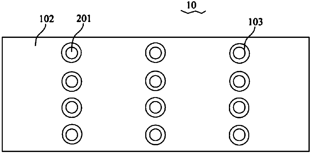
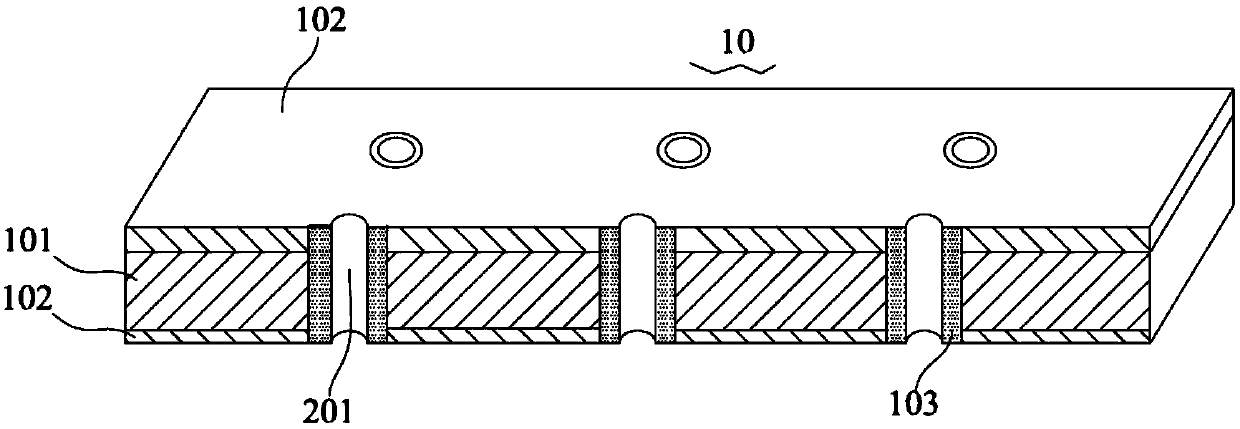
[0100] 1.1 Select a support layer with a certain thickness, drill holes in the support layer, and then form a conductive layer with a certain thickness on the surface of the support layer by vacuum evaporation, and fill the conductive layer in the holes as a conductive material, that is, one-time molding. The conductive layer is deposited on the surface of the support layer and the surface of the hole wall of the hole;
[0101] 1.2 Select a support layer with a certain thickness, form a conductive layer with a certain thickness on its surface by vacuum evaporation, then punch holes, and then fill the holes with conductive materials.
[0102] The formation conditions of the vacuum evaporation method are as follows: the support layer that has been cleaned on the surface is placed in a vacuum coating room, and the high-purity metal wire in the metal evaporation room is melted and evaporated at a high temperature of 1600 ° C to 2000 ° ...
experiment example
[0118] 1. Battery test method:
[0119] Carry out cycle life test on lithium-ion battery, the specific test method is as follows:
[0120] Charge and discharge the lithium-ion battery at two temperatures of 25°C and 45°C, that is, first charge to 4.2V with a current of 1C, and then discharge to 2.8V with a current of 1C, and record the discharge capacity of the first week; Then the battery was subjected to a 1C / 1C charge-discharge cycle for 1000 cycles, and the battery discharge capacity of the 1000th cycle was recorded, and the discharge capacity of the 1000th cycle was divided by the discharge capacity of the first cycle to obtain the capacity retention rate of the 1000th cycle.
[0121] The experimental results are shown in Table 3.
[0122] 2. Experimental method and test method of nail penetration experiment:
[0123] Nail piercing test: After the battery is fully charged, fix it, and at room temperature, insert a steel needle with a diameter of 8mm through the battery ...
PUM
| Property | Measurement | Unit |
|---|---|---|
| thickness | aaaaa | aaaaa |
| thickness | aaaaa | aaaaa |
| thickness | aaaaa | aaaaa |
Abstract
Description
Claims
Application Information
 - R&D
- Intellectual Property
- Life Sciences
- Materials
- Tech Scout
- Unparalleled Data Quality
- Higher Quality Content
- 60% Fewer Hallucinations
Browse by: Latest US Patents, China's latest patents, Technical Efficacy Thesaurus, Application Domain, Technology Topic, Popular Technical Reports.
© 2025 PatSnap. All rights reserved.Legal|Privacy policy|Modern Slavery Act Transparency Statement|Sitemap|About US| Contact US: help@patsnap.com


