Resonance suppression method of permanent magnet synchronous motor air-conditioner driving system without electrolytic capacitor
A technology of permanent magnet synchronous motor and motor drive system, which is applied in the direction of motor generator control, electronic commutation motor control, control system, etc., can solve problems such as system resonance, achieve resonance phenomenon suppression, stability improvement, and amplitude weakening Effect
- Summary
- Abstract
- Description
- Claims
- Application Information
AI Technical Summary
Problems solved by technology
Method used
Image
Examples
specific Embodiment approach 1
[0025] Specific implementation mode 1: The specific process of the resonance suppression method of the electrolytic capacitor permanent magnet synchronous motor air-conditioning drive system in this implementation mode is as follows:
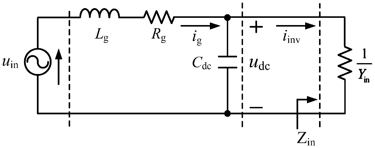
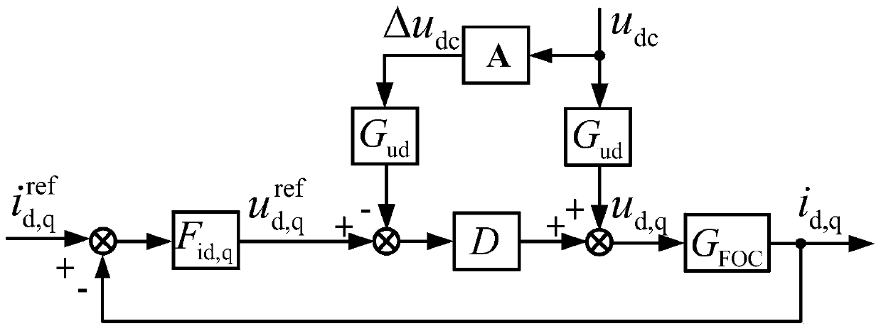
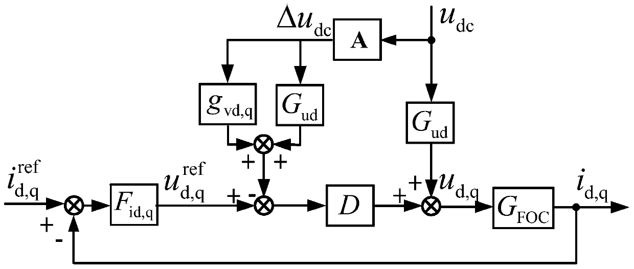
[0026] The present invention will be described in detail and completely below with reference to the accompanying drawings. to combine figure 1 and Figure 12 , the present invention proposes a resonance suppression method for an electrolytic capacitor permanent magnet synchronous motor air-conditioning drive system. The resonance suppression method is used to suppress the resonance phenomenon in the motor drive system, and specifically includes the following steps:
[0027] Step 1: The resonance phenomenon in the non-electrolytic capacitor drive system is caused by the resonance phenomenon between the DC bus capacitor and the filter reactor. In order to suppress the resonance phenomenon in the actual system, it is necessary to increase the syst...
specific Embodiment approach 2
[0034] Specific embodiment 2: The difference between this embodiment and specific embodiment 1 is that the resonance phenomenon in the non-electrolytic capacitor drive system in the step 1 is caused by the resonance phenomenon between the DC bus capacitor and the filter reactor. In the actual system In order to suppress the resonance phenomenon, it is necessary to maintain system stability and suppress resonance by increasing the system impedance. According to the parameters of the permanent magnet synchronous motor body and the control loop parameters of the vector control system, calculate the total input impedance of the permanent magnet synchronous motor drive system and the conditions for the stability of the motor drive system; the specific process is as follows:
[0035] When the permanent magnet synchronous motor is running, the impedance signal model of the motor drive system is established from the grid input side (that is, the impedance model viewed from the grid inp...
specific Embodiment approach 3
[0049] Specific embodiment three: the difference between this embodiment and specific embodiment one or two is that the G dd , G dq The expression is as follows:
[0050]
[0051]
[0052] In the formula, G FOC is the motor model equation in the dq-axis coordinate system; F id is the current controller of the d-axis; F iq is the current controller of the q-axis; A is the band-pass filter; D is the delay time of the PWM drive control signal; G ud is the counter electromotive force coefficient.
[0053] Other steps and parameters are the same as those in Embodiment 1 or Embodiment 2.
PUM
 Abstract
Description
Claims
Application Information
 - R&D
- Intellectual Property
- Life Sciences
- Materials
- Tech Scout
- Unparalleled Data Quality
- Higher Quality Content
- 60% Fewer Hallucinations
Browse by: Latest US Patents, China's latest patents, Technical Efficacy Thesaurus, Application Domain, Technology Topic, Popular Technical Reports.
© 2025 PatSnap. All rights reserved.Legal|Privacy policy|Modern Slavery Act Transparency Statement|Sitemap|About US| Contact US: help@patsnap.com


