Heat regenerator based on phase change materials and stirling cycle system
A technology of phase change materials and regenerators, which is applied in the field of Stirling cycle systems, can solve the problems of less application and no filling of regenerators, and achieve the goal of increasing heat storage, reducing thermal fatigue damage, and reducing volume Effect
- Summary
- Abstract
- Description
- Claims
- Application Information
AI Technical Summary
Problems solved by technology
Method used
Image
Examples
Embodiment 1
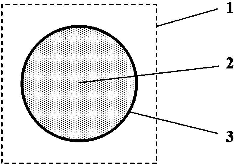
[0049] Such as figure 2 As shown, the phase change capsule 1 includes two parts: a capsule core 2 and a capsule wall 3 . The capsule core 2 is made of phase-change material, and the phase-change process occurs within the working temperature range of the regenerator, that is, the temperature of the high-temperature airflow is higher than the melting point of the phase-change material of the capsule core, and the temperature of the low-temperature airflow is lower than the melting point of the phase-change material of the capsule core, which is used for storage and release heat. The capsule wall 3 is used to separate the capsule core from the air flow, protect the capsule core, and transfer heat. Those skilled in the art can understand that the filler used in the regenerator for latent heat exchange in the present invention mainly utilizes the latent heat performance of the phase change material. That is to say, the structure of the phase-change material used as filler is not...
Embodiment 2
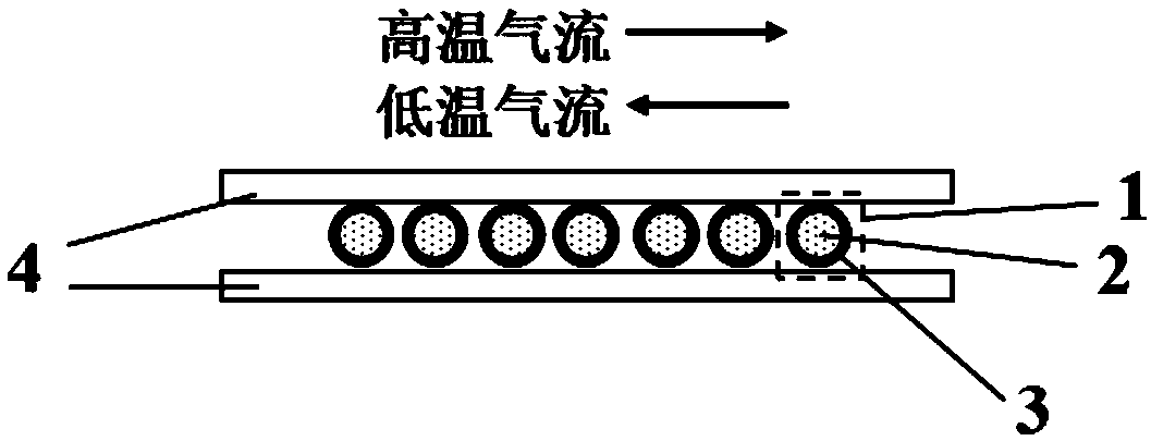
[0053] Such as image 3As shown, the regenerator shell 4 is in the shape of a flat cuboid, the height of which is equal to the outer diameter of the phase-change capsule, and a layer of phase-change capsule 1 is fixed. The phase-change capsule 1 is generally a large capsule with a particle diameter greater than 1 mm, which is convenient for fixing. The regenerator shell 4 is an air flow channel. The high-temperature air first enters the regenerator from the side of the regenerator shell and flows through the phase change capsule 1. The temperature of the capsule wall 3 rises. Because the melting point of the capsule wall material is much higher than the high temperature The airflow remains solid, and because the thermal conductivity of the wall material is high, the heat flow temperature of the high-temperature airflow can be well transmitted to the capsule core 2. Generally, the melting point of the core material is relatively low and lower than the temperature of the high-tem...
Embodiment 3
[0055] Such as Figure 4 As shown, the shape of the regenerator shell is cylindrical, square, honeycomb or circular, that is, the cross-sectional shape of the chamber formed by the regenerator shell is circular, square, honeycomb or circular. The phase-change capsule 1 is placed in the cavity formed by the shell 4 of the regenerator, and its fixing method is changed from the direct fixation of the original regenerator shell 4 to the multi-layer wire mesh 5, and each two layers of wire mesh clamp a Layer phase change capsule 1, the phase change capsule is generally a large capsule with a particle diameter greater than 1mm. The air flow enters the cavity formed by the regenerator shell 4 through the wire mesh 5 , exchanges heat with the phase change capsule 1 , and then flows out through the wire mesh on the other side. Specifically, cylindrical, square, and honeycomb shells are mainly used in α-type Stirling engines. However, in β-type and γ-type Stirling engines, an annular ...
PUM
 Abstract
Description
Claims
Application Information
 - R&D
- Intellectual Property
- Life Sciences
- Materials
- Tech Scout
- Unparalleled Data Quality
- Higher Quality Content
- 60% Fewer Hallucinations
Browse by: Latest US Patents, China's latest patents, Technical Efficacy Thesaurus, Application Domain, Technology Topic, Popular Technical Reports.
© 2025 PatSnap. All rights reserved.Legal|Privacy policy|Modern Slavery Act Transparency Statement|Sitemap|About US| Contact US: help@patsnap.com


