
Preparation method of self-humidifying membrane electrode for fuel cell

A fuel cell and self-humidification technology, applied in fuel cells, circuits, electrical components, etc., can solve the problems of increasing charge transfer resistance, reducing electrode conductivity, complicated preparation procedures, etc., and reducing electrode conductivity and resistance. effect, excellent performance, the effect of simplifying the preparation process

Inactive Publication Date: 2019-09-27
江苏乾景新能源产业技术研究院有限公司
View PDF5 Cites 5 Cited by
  • Summary
  • Abstract
  • Description
  • Claims
  • Application Information

AI Technical Summary

Problems solved by technology

In this patent, the preparation of the anode hydrophilic catalytic layer must be irradiated with purple light with a wavelength of less than 387nm for a long time. It will reduce the conductivity of the entire electrode, increase the charge transfer resistance, and affect the performance of the battery
[0006] So far, there is no way to significantly weaken the effect of doping non-conductive hydrophilic substances on battery resistance

Method used


Image

  • Preparation method of self-humidifying membrane electrode for fuel cell
  • Preparation method of self-humidifying membrane electrode for fuel cell
  • Preparation method of self-humidifying membrane electrode for fuel cell

Examples


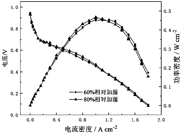
Embodiment 1

[0022] (1) Pretreatment of proton exchange membrane

[0023] Take a 3×3cm Nafion212 proton exchange membrane, first place it in 5wt.% hydrogen peroxide and treat it at 80°C for 1 hour, wash it with distilled water, then treat it in 0.5mol / L sulfuric acid solution for 1 hour, and then use After washing with distilled water, place the treated proton exchange membrane at the center of two pieces of 10×10 cm plexiglass with 2×2 cm holes, and clamp them to prevent shrinkage and deformation during the process of loading the catalyst.

[0024] (2) Preparation of anode hydrophilic catalytic layer

[0025] According to the mass ratio of 6:3:1:500, weigh 4 mg of Pt / C catalyst (40 wt.%, Johnson Matthey), 40 mg of Nafion solution (5 wt.%, DuPont), and 0.67 mg of chitin (aladdin) 1. 0.5 g of isopropanol, ultrasonically oscillated for 30 minutes, sprayed on one side of the proton exchange membrane, and dried in an oven at 75° C. for 3 hours to obtain the anode hydrophilic catalytic layer. ...

Embodiment 2

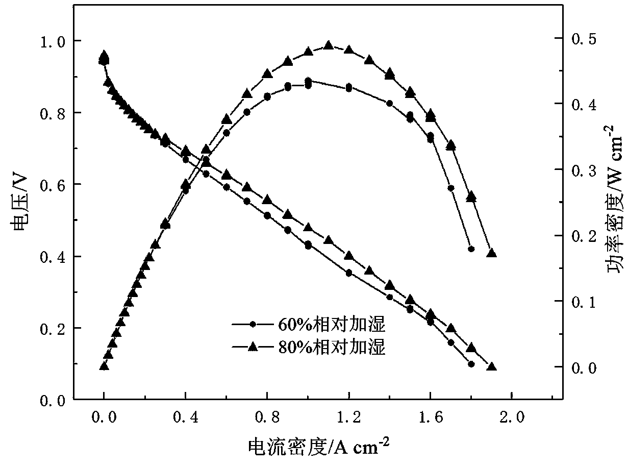
[0031] The amount of chitin added was changed to 30 wt.%, and the rest of the experimental steps and assembly test conditions were the same as in Example 1. Test results such as figure 2 , it can be seen that the highest power density of the battery reaches 435mW / cm when the relative humidity is 60%. 2 ,0.6V current density reaches 597 mA / cm 2 ;The highest power density reaches 480mW / cm at 80% relative humidity 2 , the current density reaches 707 mA / cm at 0.6V 2 .

Embodiment 3

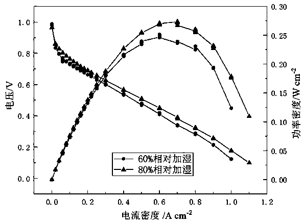
[0033]The amount of chitin added was changed to 20 wt.%, and the rest of the experimental steps and assembly test conditions were the same as in Example 1. The test results show that the highest power density of the battery reaches 459mW / cm when the relative humidity is 60%. 2 ,0.6V current density reaches 611 mA / cm 2 ;The highest power density reaches 469mW / cm at 80% relative humidity 2 ,0.6V current density reaches 628mA / cm 2 .


PUM

PropertyMeasurementUnit
particle sizeaaaaaaaaaa
thicknessaaaaaaaaaa
thicknessaaaaaaaaaa

Abstract

The invention relates to a preparation method of a self-humidifying membrane electrode for a fuel cell. The preparation process of the membrane electrode comprises the following steps: pretreating a proton exchange membrane; preparing an anode hydrophilic catalytic layer; preparing a cathode catalyst layer; respectively laminating gas diffusion layers to prepare the self-humidifying membrane electrode; wherein the anode hydrophilic material chitin can play a good role in water retention, moisture generated by reaction in the cathode catalyst layer is absorbed and retained, the proton exchange membrane is fully wetted, and good proton conduction capability of the proton exchange membrane is kept; the self-humidifying membrane electrode can have excellent performance under a low-humidity condition, the influence of adding hydrophilic substances on the electrical conductivity and resistance of the electrode is reduced, and the preparation process of the membrane electrode is simplified.

Description

technical field [0001] The invention relates to the technical field of fuel cells, in particular to a method for preparing self-humidifying membrane electrodes for fuel cells. Background technique [0002] In today's increasingly tense world of fossil energy and increasingly severe environmental problems, research on hydrogen energy and fuel cell technology has received great attention worldwide. my country's "National Medium and Long-Term Science and Technology Development Plan (2006-2020)" puts fuel cells in an important development direction in many places, and lists the preparation of basic key components of fuel cells and stack integration technology as cutting-edge technologies. As the latest generation of fuel cells, polyelectrolyte membrane fuel cells (PEMFC) have the advantages of high specific energy, low operating temperature, environmental friendliness, quick startup at room temperature, long life, etc., and are ideal power sources for mobile and portable devices...

Claims


Application Information

Patent Timeline
Patent Type & Authority Applications(China)
IPC IPC(8): H01M8/1004
CPCH01M8/1004H01M2008/1095Y02E60/50
Inventor 解政苏华能朱新坚吴曌慧
Owner 江苏乾景新能源产业技术研究院有限公司
Learn More