Ultra-wideband low-profile conformal antenna

A conformal antenna, low-profile technology, applied in the direction of antennas, antenna parts, antenna supports/mounting devices, etc., can solve problems such as beam shape distortion, affect system use, and cannot meet the requirements of antenna frequency bandwidth, etc., to achieve directional Figure stabilization effect

Inactive Publication Date: 2019-10-01
SOUTHWEST CHINA RES INST OF ELECTRONICS EQUIP
View PDF6 Cites 6 Cited by
  • Summary
  • Abstract
  • Description
  • Claims
  • Application Information

AI Technical Summary

Problems solved by technology

However, its relative bandwidth is still only 14%, which cannot meet the requirements of the antenna frequency bandwidth in the field of electronic countermeasures
[0016] In Chapter 5 of the above-mentioned literature, an electromagnetically coupled microstrip log-periodic antenna is designed using the method of h) using a frequency-invariant structure, as shown in figure 2 As shown, the working f

Method used


Image

  • Ultra-wideband low-profile conformal antenna
  • Ultra-wideband low-profile conformal antenna
  • Ultra-wideband low-profile conformal antenna

Examples


Embodiment 1

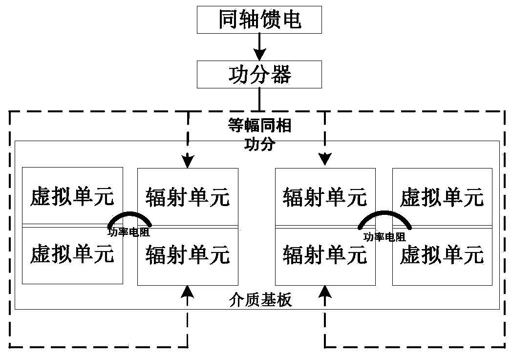
[0037] This embodiment proposes an ultra-wideband low-profile conformal antenna, such as image 3 As shown, the conformal antenna is composed of radiating elements and virtual elements. Both the radiating unit and the dummy unit are printed on a thin dielectric substrate, and the radiating units and the dummy units are connected by tight coupling, and at the end of the radiating unit, a power resistor is used to connect to the dummy unit. Finally, a power divider is used to combine the ports of multiple radiating elements with equal amplitude and in-phase to improve the gain of the conformal antenna and reduce the influence of the external environment on the direction of the conformal antenna. Wherein, the structure of the radiation unit is the same as that of the dummy unit, which can be formed in the form of microstrip antenna or dipole antenna, etc., and the dielectric substrate can be FR-4 epoxy resin board.

[0038] Due to the softness of the dielectric substrate, in ord...

Embodiment 2

[0040] This embodiment is on the basis of embodiment 1:

[0041] The antenna of this embodiment is an ultra-wideband low-profile conformal receiving antenna with a working frequency band of 0.1GHz to 0.8GHz. The simulation model is as follows Figure 5 shown.

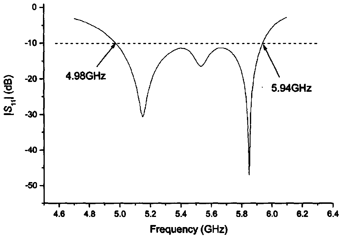
[0042] The simulation results of the standing wave coefficient are as follows: Figure 6 As shown, the bandwidth of the antenna with a Voltage Standing Wave Ratio (Voltage Standing WaveRatio, VSWR) not greater than 2.0 is 0.1 GHz-0.8 GHz, and the relative bandwidth reaches an octave of 8 times.

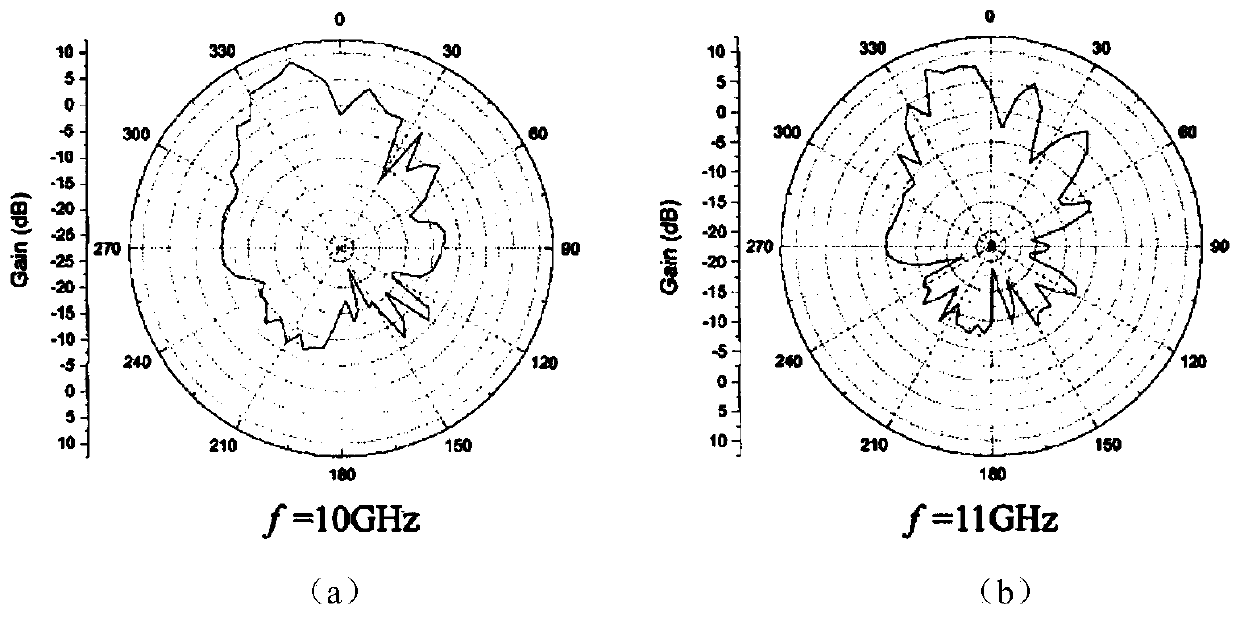
[0043] The simulation results of the direction diagram are as follows: Figure 7 As shown, (a) and (b) respectively represent the simulation results of the pattern of the azimuth plane and the elevation plane, and different curves represent the pattern of different frequencies. From the simulation results, it can be seen that the pattern of the antenna is relatively smooth in the ultra-wide frequency band of 0.1GHz to 0.8GHz...

Embodiment 3

[0045] This embodiment is on the basis of embodiment 2:


PUM


Abstract

The invention discloses an ultra-wideband low-profile conformal antenna comprising a plurality of radiating elements and a plurality of virtual units. The radiating units and the virtual units are coupled, adjacent units are tightly connected together, the radiating units are connected to the virtual units through power resistors, both the radiating units and the virtual units are printed on a dielectric substrate, and multiple ports are synthesized by a power splitter in an equal phase and same phase way. An outer side of the conformal antenna is provided with a layer of skin, an inner side is provided with a supporting structure, the supporting structure is provided with a mounting hole, and the conformal antenna is mechanically connected through the mounting hole. The relative bandwidthof the invention can reach 8 times of octave or even wider, the antenna height is only equivalent to 0.22 lambda of a center frequency point and is equivalent to 0.06 lambda of a low frequency, and the directional radiation can be achieved by using a metal plate in a machine body. The antenna directional diagram is stable in an ultra-wideband of 8 octaves, and no distortion such as inclined headand falling pits occurs.

Description

technical field [0001] The invention belongs to the technical field of communication, and in particular relates to an ultra-wideband low-profile conformal antenna. Background technique [0002] In IEEE Std145-1993, the definition of a conformal antenna is given: a conformal antenna is an antenna or antenna array that is consistent with the shape of an object. Usually, the shape of an object is non-planar, which requires that the shape of the conformal antenna is also remodelable. The microstrip antenna is composed of a ground plane, a dielectric substrate and a microstrip unit. It is usually printed on a soft substrate and has a thin thickness. Its shape has a certain degree of bendability, which is an ideal choice for conformal antennas. [0003] But microstrip antennas also have their inherent drawbacks. As a resonant antenna, it can be equivalent to a high-Q parallel resonant circuit, which means that the energy stored in the antenna structure is much larger than the ra...

Claims


Application Information

Patent Timeline
IPC IPC(8): H01Q1/38H01Q1/42H01Q23/00H01Q1/12
CPCH01Q1/1207H01Q1/38H01Q1/42H01Q23/00
Inventor 赵志强孙全国全旭林唐飞熊张登材黄迎春卓沛熊怡因
Owner SOUTHWEST CHINA RES INST OF ELECTRONICS EQUIP
Why Eureka
Try Eureka