
A Calculation Method of Groove Width of Narrow Gap Laser Filled Wire Welded Plate

A technology of groove width and laser wire filling, which is applied in laser welding equipment, welding equipment, metal processing equipment, etc., can solve the problems of large differences in the concentration of welding wire alloy elements, large welding heat input, and complex influence rules, etc., to reduce the number of tests Quantity and cycle, reduce application cycle, reduce the effect of trial and error process

Active Publication Date: 2021-01-19
XI AN JIAOTONG UNIV
View PDF4 Cites 0 Cited by
  • Summary
  • Abstract
  • Description
  • Claims
  • Application Information

AI Technical Summary

Problems solved by technology

Traditional welding techniques such as TIG and MIG have low cost and wide application range, but the welding heat input is large, resulting in high welding residual stress and deformation in the joint, which is not conducive to the control of crack defects; laser deep penetration welding is used for welding At the same time, the stability of the welding process is very sensitive to even an assembly gap of about 0.1mm, and the inherent instability of the "small hole" will also cause porosity defects, and the maximum weld penetration is limited by the power of the laser; laser / arc The hybrid welding method has a large difference in the concentration of alloy elements in the welding wire due to the wide top and bottom narrow of the weld, and seriously weakens the metal toughness of the ultra-high-strength steel weld. In addition, the laser arc composite heat source welding involves more influences and the influence rules are more complicated, which is not conducive to controlling the joint. Quality; electron beam welding has a large penetration depth and can achieve good welding results, but it needs to be welded in a vacuum environment, which greatly limits the application of this method, especially the welding production of large components
[0003] At present, the equipment investment cost of narrow-gap laser wire-filling multi-layer welding technology is much lower than that of single-pass laser deep penetration welding, and can avoid various problems existing in thick plate laser single-pass deep penetration welding. It has high quality, high efficiency and good stability. However, after determining the appropriate groove size, it is still necessary to conduct a large number of tests on the process parameters to obtain a welded joint with the expected weld width and satisfactory forming quality, and a large number of basic tests are required. Optimizing the mouth size, while the current testing of process parameters mainly relies on worker experience for optimization, which is time-consuming and labor-intensive

Method used


Image

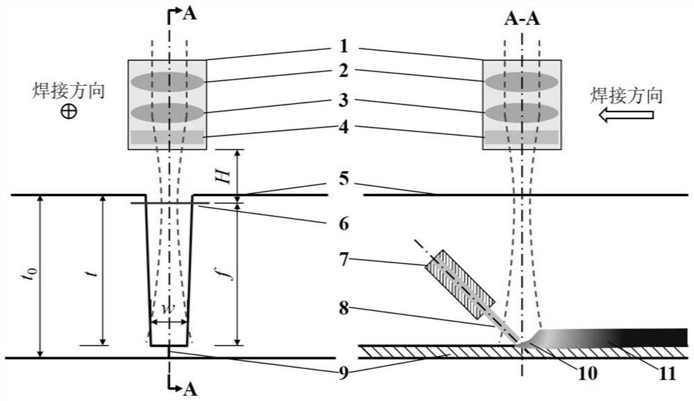
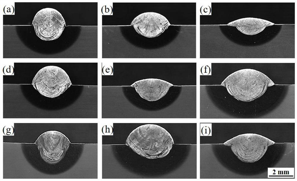
  • A Calculation Method of Groove Width of Narrow Gap Laser Filled Wire Welded Plate
  • A Calculation Method of Groove Width of Narrow Gap Laser Filled Wire Welded Plate
  • A Calculation Method of Groove Width of Narrow Gap Laser Filled Wire Welded Plate

Examples


Embodiment 1

[0072] Take the butt welding of two 300mm (length)*120mm (width)*6.6mm (thickness) D406A ultra-high-strength steel plates as an example, the length of the weld bead is 300mm. Using IPG's Nd:YAG 4kW multi-mode infrared fiber laser as a heat source, the laser beam is basically incident perpendicular to the surface of the test plate. In order to protect the laser lens group, the laser head is deflected backward by 5°. The incident fiber diameter of the laser welding head is φ200μm, and the focal length of the collimating lens is F c 150mm, focusing lens distance F 150mm, beam parameter product BPP 7.0mm*mrad, laser beam wavelength λ1070nm. The welding wire with a diameter of 1.2 mm is front-mounted, and the wire feeding mechanism sends the welding wire into the molten pool, and the angle between the wire feeding gun and the horizontal is 45°; according to formula (5), it can be obtained In order to achieve narrow-gap laser wire-filled butt welding of 6.6mm thick plates, the ga...

Embodiment 2

[0079] Taking the butt welding of two 90mm (length)*45mm (width)*20mm (thickness) D406A ultra-high-strength steel plates as an example, the length of the weld bead is 90mm. Using IPG's Nd:YAG 4kW multi-mode infrared fiber laser as a heat source, the laser beam is basically incident perpendicular to the surface of the test plate. In order to protect the laser lens group, the laser head is deflected backward by 5°. The incident fiber diameter of the laser welding head is φ200μm, and the focal length of the collimating lens is F c 150mm, focusing lens distance F 150mm, beam parameter product BPP 7.0mm*mrad, laser beam wavelength λ1070nm. The welding wire with a diameter of 1.2mm is front-mounted, and the welding wire is sent into the molten pool by the wire feeding mechanism, and the angle between the wire feeding gun and the horizontal is 45°. According to formula (5), we can get In order to achieve narrow gap laser wire-filled butt welding of 20mm thick plates, the gap widt...


PUM

PropertyMeasurementUnit
thicknessaaaaaaaaaa
thicknessaaaaaaaaaa
widthaaaaaaaaaa

Abstract

The invention discloses a method for calculating the groove width of a narrow gap laser filler wire welded plate. According to laser beam transmission characteristic parameters, a proper laser defocusamount range for the thickness of a to-be-welded plate can be obtained; according to the defocus amount range, a well-formed laser filler wire single-pass surfacing process parameter window and the welding bead width variation range are obtained on a flat plate of the same material; the expected well-formed groove width is obtained according to the sidewall melting condition and spatial interference analysis; and a groove is machined in a to-be-welded test plate, and narrow gap laser filler wire welding is completed. The well-formed ultra-thick plate narrow gap laser filler wire welding process parameters can be quickly calculated, and the number and cycle of experiments required for process optimization are greatly reduced. According to the specified characteristic parameters of laser filler wire welding equipment, whether narrow gap welding of the corresponding thick plate can be completed or not is judged, the process parameter window is given, and the application period of the narrow gap laser filler wire welding technology is greatly reduced.

Description

technical field [0001] The invention belongs to the technical field of metal material welding, and in particular relates to a method for calculating the groove width of a narrow-gap laser wire-filled welding plate. Background technique [0002] With the continuous improvement of service performance requirements for large-scale components in industries such as aviation, aerospace, automobiles, and ships, higher technical goals have been put forward for the welding quality and welding deformation control of large-thickness plates. Traditional welding techniques such as TIG and MIG have low cost and wide application range, but the welding heat input is large, resulting in high welding residual stress and deformation in the joint, which is not conducive to the control of crack defects; laser deep penetration welding is used for welding At the same time, the stability of the welding process is very sensitive to even an assembly gap of about 0.1mm, and the inherent instability of ...

Claims


Application Information

Patent Timeline
Patent Type & Authority Patents(China)
IPC IPC(8): B23K26/342B23K26/70B23K26/21
CPCB23K26/21B23K26/342B23K26/70B23K26/702
Inventor 方学伟杨健楠张林杰王常幸白浩任传奇吴军卢秉恒
Owner XI AN JIAOTONG UNIV
Learn More