
Compressed carbon dioxide energy storage system with heat storage cycle in dual underground gas storage chambers

A carbon dioxide, energy storage system technology, applied in geothermal energy systems, steam engine installations, liquid variable capacity machinery, etc., can solve the problems of low energy storage efficiency, low energy storage density, etc. Effect

Inactive Publication Date: 2019-10-18
NORTH CHINA ELECTRIC POWER UNIV (BAODING)
View PDF5 Cites 6 Cited by
  • Summary
  • Abstract
  • Description
  • Claims
  • Application Information

AI Technical Summary

Problems solved by technology

[0008] The purpose of the present invention is to disclose a compressed carbon dioxide energy storage system with a heat storage system with double underground gas storage chambers, which uses carbon dioxide instead of air as the working medium to solve the problems of low energy storage density and low energy storage efficiency. The saline water layers at different depths are used as carbon dioxide gas storage chambers, using geothermal energy to heat high-pressure carbon dioxide, eliminating the need for heat accumulators in the energy storage system, and the system’s working medium carbon dioxide is recycled, and the heat exchange medium is used in the process of energy storage and release. Therefore, the system can solve the problems of low energy storage density and low energy storage efficiency of the energy storage system, and at the same time achieve the purpose of economy, environmental protection and high efficiency.

Method used


Image

  • Compressed carbon dioxide energy storage system with heat storage cycle in dual underground gas storage chambers
  • Compressed carbon dioxide energy storage system with heat storage cycle in dual underground gas storage chambers

Examples


Embodiment Construction

[0028] The present invention provides a compressed carbon dioxide energy storage system with double underground gas storage chambers and a heat storage system. The present invention will be further described below in conjunction with the accompanying drawings and specific implementation methods.

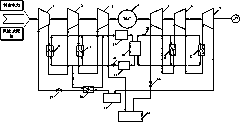
[0029] The present invention can be realized based on the system, and its specific structure is as figure 1 As shown, the system consists of compressor 1, compressor 2, compressor 3, generator / motor, expansion turbine 1, expansion turbine 2, expansion turbine 3, interstage cooler 1, interstage cooler 2 , precooler, interstage reheater 1, interstage reheater 2, underground low-pressure gas storage room, underground high-pressure gas storage room, heat storage tank, cold storage tank, heat pump (by compressor 4, condenser, expansion Valve and evaporator), throttle valve 1, throttle valve 2, throttle valve 3, throttle valve 4, the specific operation process is as follows:

[0030] Such...


PUM


Abstract

The invention discloses a novel compressed carbon dioxide energy storage system. The system takes carbon dioxide as a working medium, and comprises main equipment such as a compressor (unit), an expansion turbine (unit), underground gas storage chambers and a heat exchanger. In order to prevent carbon dioxide from being discharged into atmosphere, the system adopts two underground salt water layers as the gas storage chambers, the high-pressure gas storage chamber is used for storing supercritical carbon dioxide released by the compressor, and the low-pressure gas storage chamber is used for storing carbon dioxide released by the expansion turbine, so that a sealed energy storage system is formed; a working medium in the high-pressure gas storage chamber can be heated by terrestrial heat,and compression heat generated in a compression process and heat of a working medium in an outlet of the low-pressure gas storage chamber can be collected, so that the working medium provides energy for reheating a secondary turbine and a tertiary turbine in an energy release process after being heated by a heat pump. From the above, the system adopts the underground salt water layers as the underground gas storage chambers to store carbon dioxide, so that pollutants are not generated in an operation process, and therefore, the effects of being economical, environmentally friendly and energy-saving are achieved. The compressed carbon dioxide energy storage system is as shown in figure 1.

Description

technical field [0001] The invention belongs to the field of compressed carbon dioxide energy storage systems, and particularly relates to a compressed carbon dioxide energy storage system in which saline water layers at different depths of the ground act as high and low pressure gas storage chambers respectively; meanwhile, it relates to a heat storage system with a heat pump subsystem , to realize cascade utilization and recycling of heat in the energy storage system. Background technique [0002] At present, compressed air energy storage technology was born in the 1970s, and it is a relatively mature and feasible large-scale energy storage technology. Its working process is: when the power consumption is low, the compressor uses the excess electric energy to compress the air in the atmospheric environment, converts the electric energy into the internal energy of the air and stores it in the air storage room, and when the power consumption peaks, the air in the air storage...

Claims


Application Information

Patent Timeline
IPC IPC(8): F04B37/18F04B41/02F03G4/00F01K27/00F01K25/10F01D15/10
CPCF01D15/10F01K25/103F01K27/00F04B37/18F04B41/02Y02E60/16
Inventor 何青郝银萍路唱杜冬梅
Owner NORTH CHINA ELECTRIC POWER UNIV (BAODING)
Learn More