Optoelectronic modulator and optoelectronic interconnection interface

A photoelectric modulator and optical modulation technology, applied in the field of optical communication, can solve problems affecting high-speed signal transmission, difficult control of signal integrity, and reflection of electrical signal loss

Inactive Publication Date: 2019-10-18
SHANGHAI JIAO TONG UNIV
View PDF9 Cites 0 Cited by
  • Summary
  • Abstract
  • Description
  • Claims
  • Application Information

AI Technical Summary

Problems solved by technology

[0003] However, the traditional MZM contains two sets of long-distance transmission lines and PN junctions. The high-speed signal of the electric driver is transmitted in the transmission line, and the optical speed matching is realized by controlling the impedance of the transmission line. Both quality and signal integrity place high demands on
First of all, for traditional MZM, the electric driver not only needs to drive the phase shifter in the optical modulator, but also drives two long-distance metal wires and terminal matching loads. Therefore, the electric driver must not only have a high signal gain to To meet the requirements of the phase shifter in MZM, it must also have a strong enough drive capability; secondly, when high-speed electrical signals are transmitted in the transmission line, it is inevitable to encounter interference from external noise and uncontrollable process disturbances. With the extension of th...

Method used


Image

  • Optoelectronic modulator and optoelectronic interconnection interface
  • Optoelectronic modulator and optoelectronic interconnection interface
  • Optoelectronic modulator and optoelectronic interconnection interface

Examples


Embodiment Construction

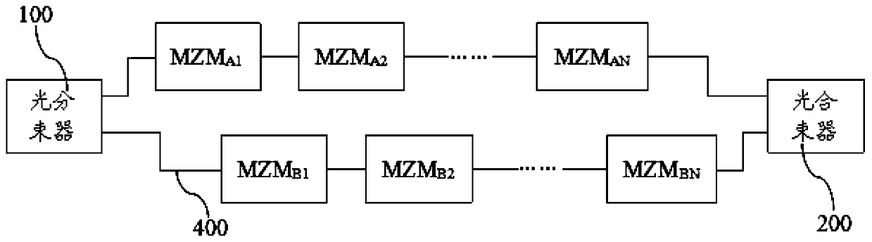
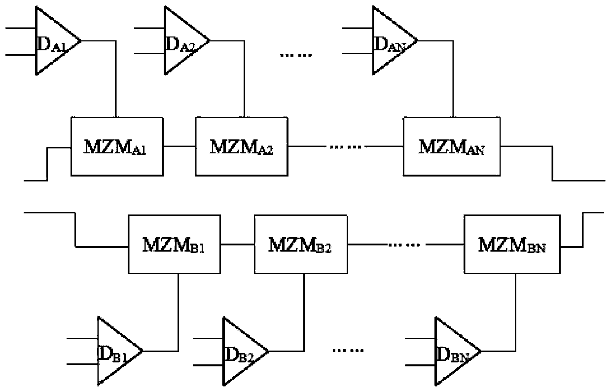
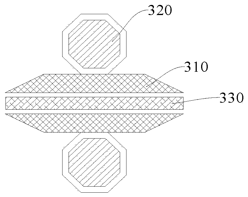
[0029] The following is attached Figures 1 to 6 and specific embodiments, the photoelectric modulator and the photoelectric interconnection interface proposed by the present invention will be further described in detail. Advantages and features of the present invention will be apparent from the following description and claims. It should be noted that the drawings are in a very simplified form and all use imprecise scales, which are only used to facilitate and clearly assist the purpose of illustrating the embodiments of the present invention. In order to make the objects, features and advantages of the present invention more comprehensible, please refer to the accompanying drawings. It should be noted that the structures, proportions, sizes, etc. shown in the drawings attached to this specification are only used to match the content disclosed in the specification, for those who are familiar with this technology to understand and read, and are not used to limit the implement...


PUM


Abstract

The invention provides a photoelectric modulator and a photoelectric interconnection interface. The photoelectric modulator comprises an optical beam splitter, an optical beam combiner and two opticalmodulation branches connected in parallel. The light beam splitter is provided with two output ends, one output end is connected with the input end of one light modulation branch, and the other output end is connected with the input end of the other light modulation branch; the light beam combiner is provided with two input ends, one input end is connected with the output end of one light modulation branch, and the other input end is connected with the output end of the other light modulation branch; and each light modulation branch comprises a plurality of Mach-Zehnder modulators which are connected in series. According to the invention, the requirement on the driving capability of the electric driver is reduced, so that the electric signal (driving signal) does not need to be remotely transmitted, the complexity of signal integrity analysis is reduced, and the propagation loss of the electric signal (driving signal) is reduced.

Description

technical field [0001] The invention relates to the technical field of optical communication, in particular to an optoelectronic modulator and an optoelectronic interconnection interface. Background technique [0002] With the development of high-performance computing and big data, the requirements for communication bandwidth in modern society are increasing day by day. As an emerging interface technology, optoelectronic interconnection technology, with its excellent high-speed signal transmission capability and ultra-high system Data storage and other aspects have been widely used. Optoelectronic interconnection technology includes optical modulators and electrical drivers. For optical modulators, the most mature technology is Mach-Zehnder Modulator (MZM) design technology. One MZM divides the light into two groups, and modulates by applying an anti-phase high-speed signal on each group of optical paths through an electric driver, so that the two groups of optical signals ...

Claims


Application Information

Patent Timeline
IPC IPC(8): H04B10/516G02F1/21
CPCG02F1/21G02F1/212H04B10/516
Inventor 刘永超纪鹏飞林文淼何卫锋宗诚毛志刚
Owner SHANGHAI JIAO TONG UNIV
Why Eureka
Try Eureka