Insulated electric wire, production method therefor, coil and coil production method using same

A technology of insulated wires and insulating coatings, applied in the direction of insulated cables, cable/conductor manufacturing, inductor/transformer/magnet manufacturing, etc., which can solve the problems of poor insulation or heat resistance, insufficient adhesion, and high manufacturing costs. Problems, to achieve the effect of excellent insulation properties or heat resistance, excellent adhesion, and maintain hardness

Active Publication Date: 2019-10-18
MITSUBISHI MATERIALS CORP
View PDF9 Cites 1 Cited by
  • Summary
  • Abstract
  • Description
  • Claims
  • Application Information

AI Technical Summary

Problems solved by technology

[0010] However, the resin used in the undercoat layer of the insulated wire disclosed in Patent Document 1 is generally inferior in heat resistance and insulation performance to the resin covered by the outer layer.
In addition, when an insulated wire with a primer layer is used as a coil, there is a problem that when the coating on the outer side of the bend becomes thinner due to edge-to-edge bending, compared with an insulated wire with the same film thickness and no primer layer , there is a tendency for the insulation or heat resistance of the curved outer periphery to deteriorate
In order to solve this problem, it is considered to increase the total thickness of the coating film composed of the primer layer and its outer layer, but there are various problems as follows: if the coating film is thickened, the coating film on the inside of the bend will be damaged when the bending process is performed. Compression causes wrinkles; in order to thicken the coating, multiple dipping coatings must be performed, but the number of times of drying increases and the drying time becomes longer; the adhesion becomes poor due to the formation of an oxide layer at the interface between the conductor and the coating; and due to the coating become thicker, and the manufacturing cost becomes higher, etc.
[0011] In addition, in the winding wire shown in Patent Document 2, the adhesiveness is improved by providing an engaging portion between the inner film and the outer film, but the parts where peeling of the inner film is most likely to occur are the metal as a conductor and the metal as an insulator. However, in this method, it is not possible to sufficiently improve the adhesion to the lead wire of the inner coating in the flat wire subjected to the edge-to-edge bending process.
[0012] Furthermore, in the method for forming a multilayer anionic electrodeposition coating film shown in Patent Document 3, when forming a multilayer coating film by electrodeposition, it is described that excellent adhesion resistance is imparted to the coating film of the first coating layer. method, and described in order to achieve good adhesion, the amount of the curing agent is set to an appropriate amount, but for improving the adhesion of the coating film of the first coating film of the flat conductor wire subjected to edge-to-edge bending processing Inadequate and not suitable for systems that do not inherently use curing agents

Method used


Image

  • Insulated electric wire, production method therefor, coil and coil production method using same
  • Insulated electric wire, production method therefor, coil and coil production method using same
  • Insulated electric wire, production method therefor, coil and coil production method using same

Examples


Embodiment

[0066] Next, examples of the present invention will be described in detail together with comparative examples.

[0067]

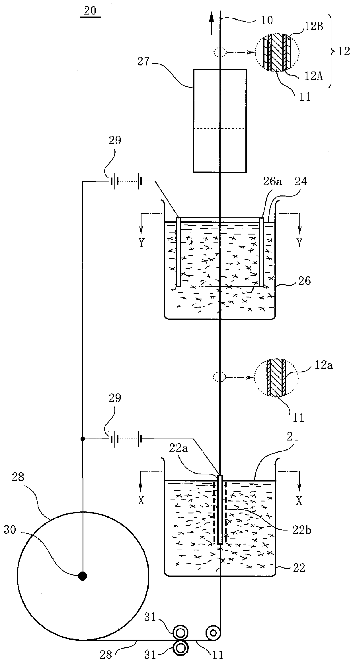
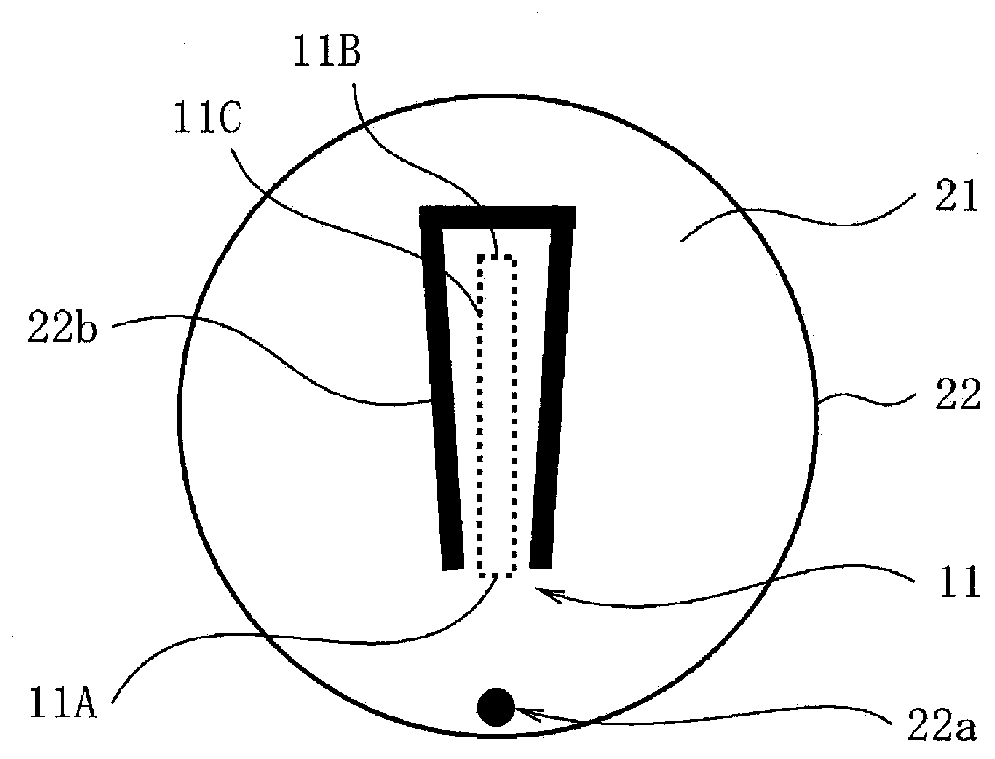
[0068] pass figure 2 In the illustrated electrodeposition coating apparatus, an insulating coating is applied to a flat copper wire having a thickness of 1.5 mm and a width of 6.5 mm as a conductor wire. As the first electrodeposition solution, a water-dispersed insulating electrodeposition paint containing polyamideimide (PAI) having a urethane skeleton of 2% by mass was prepared and stored in the first electrodeposition tank. In addition, a water-dispersed insulating electrodeposition paint containing 2% by mass of PAI was prepared as a second electrodeposition solution, and stored in a second electrodeposition tank. Such as image 3 As shown, a cathode rod is configured in the first electrodeposition tank, such as Figure 4 As shown, a semicylindrical cathode plate is disposed in the second electrodeposition tank. Such as image 3 and Figure 4 ...

Embodiment 2~6

[0070]

[0071] In addition to changing the main components of the first and second electrodeposition solutions, the long side / short side of the flat conductor wire, the diameter of the flat conductor wire converted to a round wire, and the manufacturing conditions of the insulated wire, as shown in Table 1 Outside In the same manner as in Example 1, insulated electric wires of Examples 2 to 6 and Comparative Examples 1 to 3 were produced. In Example 4, an insulated wire was produced using a water-dispersed insulating electrodeposition paint containing PI having a siloxane skeleton as the first electrodeposition liquid. In addition, in Comparative Examples 1 to 3, the flat conductor wire was not passed through the first electrodeposition solution, but only the second electrodeposition solution was passed to manufacture an insulated wire. At this time, the electrodeposition tank is as follows Figure 5 As shown, it is circular in plan view, and a cylindrical cathode plate 36...


PUM

PropertyMeasurementUnit
thicknessaaaaaaaaaa
thicknessaaaaaaaaaa
thicknessaaaaaaaaaa

Abstract

This insulated electric wire comprises an insulation coat covering a flat rectangular conductor wire whereof the transversal cross-sectional shape is rectangular. The insulation coat comprises an inner layer covering the surface of the flat rectangular conductor wire, and an outer layer covering the surface of the inner layer. In the rectangular transversal cross section of the flat rectangular conductor wire, among two short sides opposing one another and having an identical length, one of the short sides is covered by the inner layer whereof the thickness (t1) is greater than the thickness (t2) of the inner layer covering the other short side (which includes t2=0). The elastic modulus of the inner layer is smaller than the elastic modulus of the outer layer, or the yield stress of the inner layer is smaller than the yield stress of the outer layer. Alternatively, the elastic modulus and the yield stress of the inner layer are both smaller than the elastic modulus and the yield stressof the outer layer.

Description

technical field [0001] The present invention relates to an insulated wire for coiling which is formed by covering a conductor wire with an insulating film having a two-layer structure, and a method for manufacturing the same. More specifically, it relates to an insulated wire having excellent adhesion between an insulating coating on the inner side of a bend and a conductor wire during bending, and a method for manufacturing the same. Still more in detail, it is related with the manufacturing method of the coil using an insulated electric wire, and a coil. [0002] This application claims priority based on Patent Application No. 2017-055389 for which it applied in Japan on March 22, 2017, and uses the content here. Background technique [0003] In recent years, for hybrid vehicles and electric vehicles, the performance of reactors and motors has been demanded. Along with this, insulated wires for coils used in reactors and motors have changed from coil wires with a circula...

Claims


Application Information

Patent Timeline
Patent Type & Authority Applications(China)
IPC IPC(8): H01B7/02C09D5/44C09D179/08H01B13/00H01F5/06H01F27/32
CPCH01B7/08H01B7/0216H01B3/306Y02T10/64H01F27/32C09D179/08H01F41/066H01F5/06C09D5/44H01B7/02
Inventor 漆原诚工藤泰彦饭田慎太郎樱井英章
Owner MITSUBISHI MATERIALS CORP
Why Eureka
Try Eureka