
Method for electrolytic machining of microtexture

A technology of micro-texture and electrolyte, applied in the direction of electric processing equipment, electrochemical processing equipment, metal processing equipment, etc., can solve the problems of difficult mask pressing and complicated mask preparation process, so as to reduce stray corrosion, The effect of low process cost and reduced cumbersome process

Inactive Publication Date: 2019-10-25
HENAN POLYTECHNIC UNIV
View PDF6 Cites 3 Cited by
  • Summary
  • Abstract
  • Description
  • Claims
  • Application Information

AI Technical Summary

Problems solved by technology

[0004] The purpose of the present invention is to propose a method based on conductive metal microparticles as a mask, aiming at the complex mask preparation process, the difficulty of mask pressing on complex curved surfaces, and the shortcomings of actual implementation in the existing method of mask electrolytic processing micro-texture. The method of electrolytic processing micro-texture, in this method, the mask preparation is simple, the process cost is low, the molding speed is faster, and the processing efficiency is higher

Method used


Image

  • Method for electrolytic machining of microtexture
  • Method for electrolytic machining of microtexture
  • Method for electrolytic machining of microtexture

Examples


Embodiment Construction

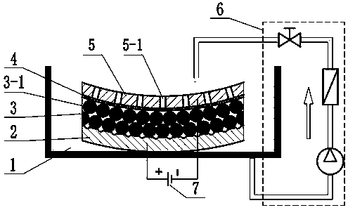
[0027] Attached below figure 1 The specific implementation process of the present invention is further described.

[0028] (1) Immerse the workpiece anode 2 in the electrolyte 1, take an appropriate amount of metal titanium particles 3-1 with a particle size of 0.2mm after wetting with the electrolyte 1, and spread it on the surface of the workpiece anode 2, and vibrate slightly to make it Form a layer 3 of uniformly arranged metal particles on the surface of the workpiece anode 2;

[0029] (2) A nylon mesh 4 with a mesh number of 150 mesh and a thickness of 0.1 mm is tightly attached to the lower surface of the metal mesh-shaped tool cathode 5 facing the metal titanium particles 3-1, and the tool cathode 5 is tightly pressed on the On the metal titanium particle layer 3, the nylon mesh 4 is placed between the tool cathode 5 and the metal titanium particle layer 3, and the metal particle 3-1 forms a metal particle layer 3 with a thickness of about 0.5mm through the pressing e...


PUM

PropertyMeasurementUnit
particle diameteraaaaaaaaaa
thicknessaaaaaaaaaa
thicknessaaaaaaaaaa

Abstract

The invention discloses a method for electrolytic machining of a microtexture. The method mainly includes the following steps that S1, a workpiece anode is immersed in electrolytes, and metal particles are laid flatly on the surface of the workpiece anode to form an equivalent thickness metal particle layer; S2, a tool cathode attached with electric insulation cloth is tightly attached to the metal particle layer, and the electric insulation cloth is disposed between the tool cathode and the metal particle layer; S3, the workpiece anode is connected with the positive pole of a power supply, and the tool cathode is connected with the negative pole of the power supply; S4, the electrolytes are supplied into the metal particle layer through an electrolyte circulating system and flow circularly in a machining gap formed between the workpiece anode and the tool cathode; and S5, the power supply is switched on for electrolytic machining, when machining requirements are met, the power supplyis disconnected, electrolyte supply stops, the workpiece anode is taken out, and machining is completed. The method has the advantages that mask preparation is simple, the application range is wide, and microtextures with uniform sizes and good profiles can be prepared on planes and curved surfaces.

Description

technical field [0001] The invention relates to the field of electrolytic machining, in particular to a method for electrolytic machining of micro-textures. Background technique [0002] Textured metal surfaces have attracted much attention in the fields of friction, heat transfer, wetting and biomedicine due to their excellent wear resistance, heat transfer properties, wettability and biocompatibility. One of the research hotspots in industry and academia. The current manufacturing processes for microstructure features mainly include high-energy beam (such as laser beam, electron beam, etc.) processing, micromachining, chemical etching, and mask electrolytic processing. Mask electrolytic machining is the most commonly used method in electrolytic machining of micropits, but the process of making the mask is very complicated, the operation is cumbersome, and the process cost is high. The machining of complex-shaped curved bodies remains a challenge for this technology becau...

Claims


Application Information

Patent Timeline
Patent Type & Authority Applications(China)
IPC IPC(8): B23H3/00B23H11/00
CPCB23H3/00B23H11/00
Inventor 明平美张云燕秦歌闫亮陈旭蔡锦涛张新民申继文
Owner HENAN POLYTECHNIC UNIV
Learn More