Wet desulfurization, denitration and absorption apparatus
A desulfurization, denitrification, and absorption device technology, applied in separation methods, chemical instruments and methods, gas treatment, etc., can solve the problems of unreasonable device processing flow, insufficient gas-liquid mixing, and large amount of ammonia escape in the gas phase, etc., to improve oxidation efficiency, less ammonia overflow, and high denitrification efficiency
- Summary
- Abstract
- Description
- Claims
- Application Information
AI Technical Summary
Problems solved by technology
Method used
Image

Examples
Embodiment 1
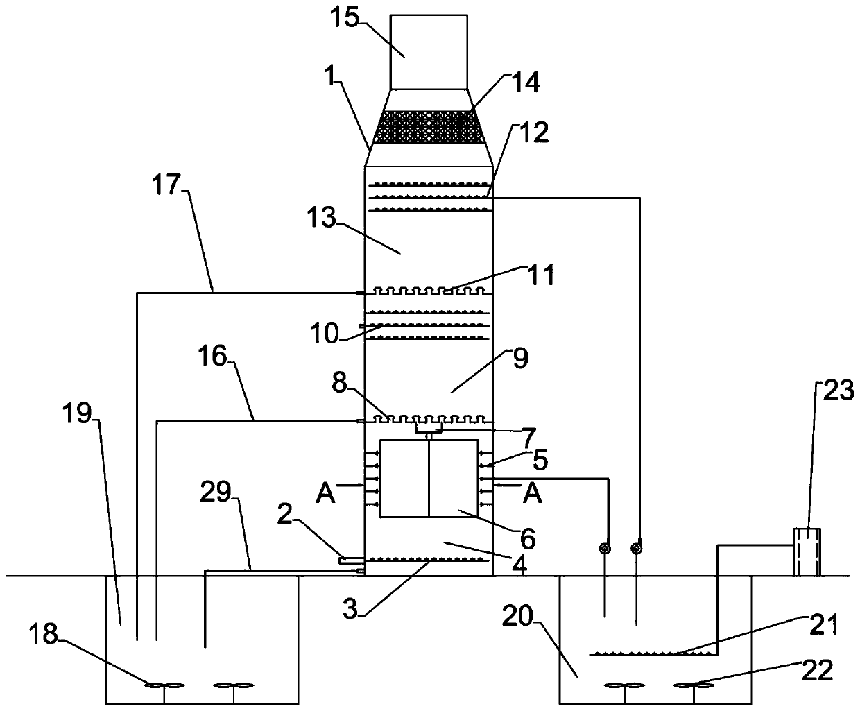
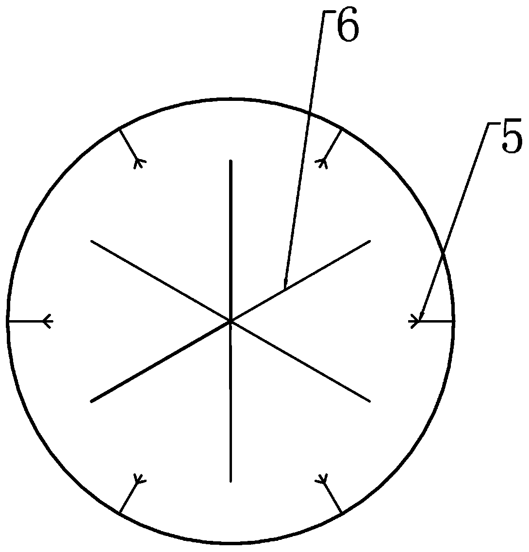
[0038] As a kind of desulfurization and denitrification absorption device of the embodiment of the present invention, such as figure 1 , figure 2 , image 3 , Figure 4 As shown, the desulfurization and denitrification absorption device includes a desulfurization and denitrification tower 1, and the flue gas inlet 2 is arranged at the lower part of the side wall of the desulfurization and denitrification tower. 4. The first gas cap layer 8, the ammonia spray distribution layer 9, the second gas cap layer 11, the ammonia absorption spray layer 13, the mist eliminator 14, and the flue gas outlet 15;
[0039] The desulfurization and denitrification absorption device also includes an oxidant supply pool 20, the oxidant supply pool is provided with a hydrogen peroxide input pipe and stores a hydrogen peroxide solution, the bottom of the oxidant supply pool is provided with an ozone uniform distribution pipe 21, and the ozone uniform distribution pipe is connected to the ozone T...
Embodiment 2
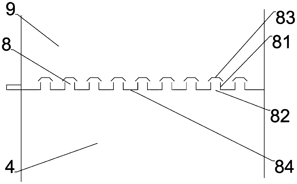
[0050] As a kind of desulfurization and denitrification absorption device of the embodiment of the present invention, such as Figure 5 As shown, the only difference between this embodiment and Embodiment 1 is: the catalyst plate is a plate with a wavy vertical section.
[0051] The desulfurization and denitrification absorption device of this embodiment adopts a wavy plate in vertical section, which can make the hydrogen peroxide solution stay on the catalyst for a longer time, so that the upwardly flowing flue gas is fully in contact with the large specific surface area of hydrogen peroxide. , improve oxidation efficiency, desulfurization efficiency and denitrification efficiency are higher than those in Example 1.
PUM
| Property | Measurement | Unit |
|---|---|---|
| Aperture | aaaaa | aaaaa |
| Angle | aaaaa | aaaaa |
Abstract
Description
Claims
Application Information
 - Generate Ideas
- Intellectual Property
- Life Sciences
- Materials
- Tech Scout
- Unparalleled Data Quality
- Higher Quality Content
- 60% Fewer Hallucinations
Browse by: Latest US Patents, China's latest patents, Technical Efficacy Thesaurus, Application Domain, Technology Topic, Popular Technical Reports.
© 2025 PatSnap. All rights reserved.Legal|Privacy policy|Modern Slavery Act Transparency Statement|Sitemap|About US| Contact US: help@patsnap.com