Piezochromism effect-based vibration visual sensor

A piezochromic and piezoelectric sensor technology, applied in the field of sensors, can solve the problems of no passive pressure visualization, high discoloration efficiency, high discoloration speed, and high energy consumption of external power supply, and achieves good transmittance, fast response speed, ionic Fast transfer effect

Inactive Publication Date: 2019-11-08
NANJING UNIV OF SCI & TECH
View PDF19 Cites 1 Cited by
  • Summary
  • Abstract
  • Description
  • Claims
  • Application Information

AI Technical Summary

Problems solved by technology

However, there are some problems in this technology. The device needs an external voltage, and the passive pressure visualization is not realized. The energy consumption is relatively high, and the organic electrochromic material used is not as high as the color changing efficiency and the color changing spe

Method used


Image

  • Piezochromism effect-based vibration visual sensor
  • Piezochromism effect-based vibration visual sensor
  • Piezochromism effect-based vibration visual sensor

Examples


Embodiment 1

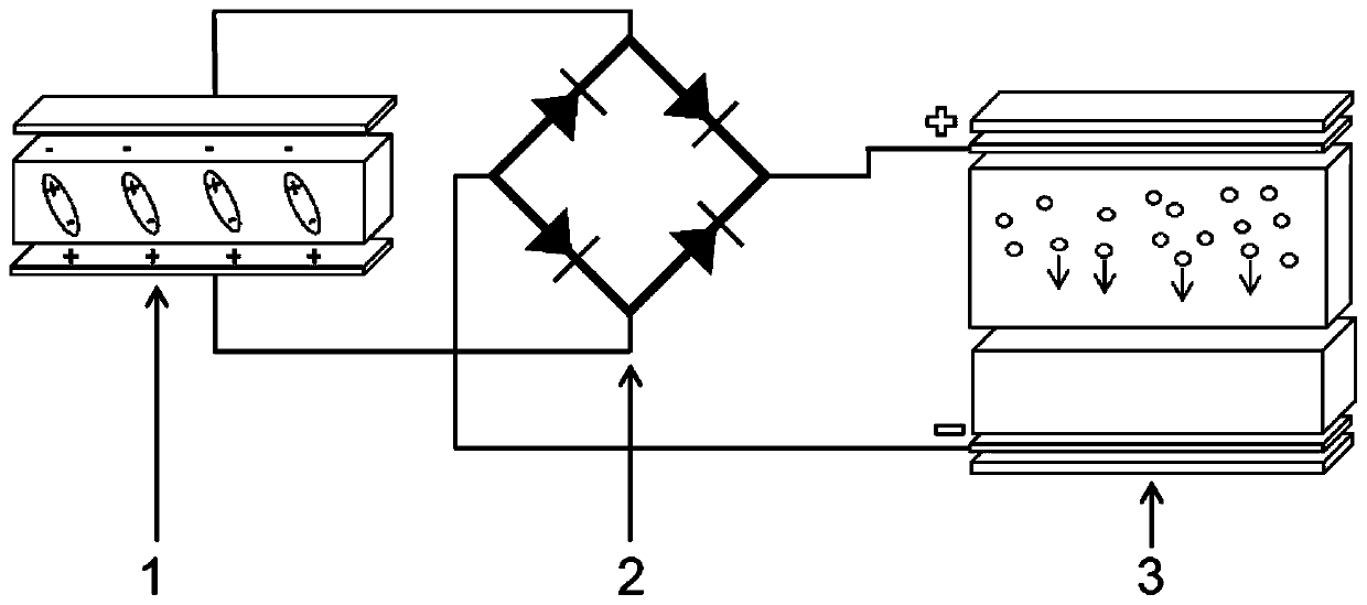
[0036] In a specific embodiment, the present invention relates to the high-efficiency inorganic piezoelectric material used in the vibration visualization sensor is lead zirconate titanate piezoelectric material (Pb(Zr 1-x Ti x )O 3 , 00.52 Ti 0.48 o 3 . The electrochromic material is tungsten trioxide WO 3 . Connect the flexible PZT piezoelectric sensor to the AC input of the rectifier, and the negative pole of the DC output of the rectifier to WO 3 Electrochromic device lower electrode connection, positive and WO 3 Electrode connection on electrochromic device.

[0037] Fluorophlogite (AlF) with a thickness of 0.05mm to 0.1mm 2 o 10 Si 33 A PZT thick film of more than 2 μm is deposited on the Mg) substrate, and then Pt interdigitated electrodes are prepared by magnetron sputtering on it, and finally the two are encapsulated by polymethyl methacrylate (PMMA).

[0038] On a polyethylene terephthalate / indium tin oxide (PET / ITO) substrate, the metal tungsten with a pu...

Embodiment 2

[0042] In a specific embodiment, the present invention relates to that the high-efficiency inorganic piezoelectric material used in the vibration visualization sensor is lead magnesium niobate-lead titanate PMN-PT. The electrochromic material is tungsten trioxide WO 3 . Connect the PMN-PT piezoelectric sensor to the AC input of the rectifier, and the negative pole of the DC output of the rectifier to WO 3 Electrochromic device lower electrode connection, positive and WO 3 Electrode connection on electrochromic device.

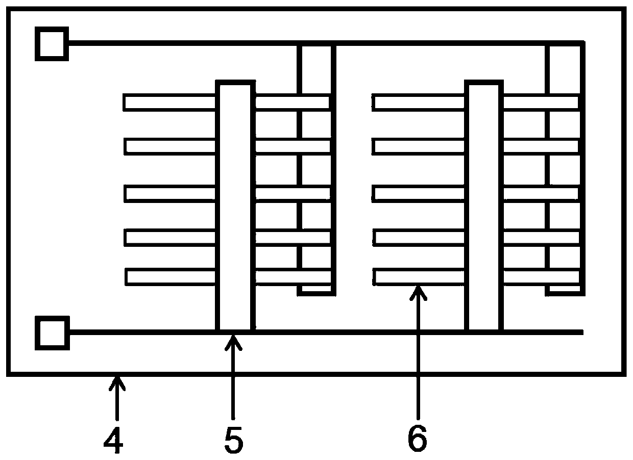
[0043] image 3 It is a structural schematic diagram of the flexible PMN-PT piezoelectric sensor in the embodiment. It is formed by combining 10 pieces of PMN-PT single chips 6 and upper and lower electrodes 5 on a polypropylene plastic substrate (PP) substrate 4 and then packaging.

[0044] Figure 4 is the flexible WO in the example 3 Schematic diagram of the structure of the electrochromic device. From top to bottom are PET substrate 4, transparent I...


PUM


Abstract

The invention belongs to the field of sensors, and particularly relates to a piezochromism effect-based vibration visual sensor. The piezochromism effect-based vibration visual sensor comprises a flexible substrate, a piezoelectric sensor, a rectifier and an electrochromism device, wherein the piezoelectric sensor, the rectifier and the electrochromism device are arranged on the flexible substrate, the piezoelectric sensor is connected with an AC input end of the rectifier, a DC output end of the rectifier is connected with the electrochromism device, so that a vibration signal is converted tocolor response. The fabricated vibration visual sensor is flexible and is resistant to bending, a piezoelectric signal and an electrochromism signal which are generated under a bending condition areapproximate to a numerical value in a smooth state, and the vibration visual sensor can be completely attached onto a surface of a vibration object.

Description

technical field [0001] The invention belongs to the field of sensors, in particular to a vibration visualization sensor based on piezochromic effect. Background technique [0002] In our daily life, vibration is ubiquitous, which brings many hazards to the structural health of roads, bridges and machines, as well as people's life safety, but real-time monitoring of pressure is still a great challenge. In recent years, with the rapid development of sensor technology, real-time structural health monitoring systems based on various monitoring technologies have been widely used in engineering fields such as bridges and high-rise buildings. Among them, piezoelectric accelerometers are common vibration-based structural health monitoring devices, but piezoelectric accelerometers are cumbersome and time-consuming to operate, and have high-power data acquisition systems, so piezoelectric accelerometers are expensive and inconvenient to operate. Another major challenge is that they r...

Claims


Application Information

Patent Timeline
IPC IPC(8): G01L1/16G01H11/08G02F1/1514
CPCG01H11/08G01L1/16G02F1/1514
Inventor 陈轩汪尧进杨娜娜汪洋杨斌文鑫荣
Owner NANJING UNIV OF SCI & TECH
Why Eureka
Try Eureka