A fully automatic welding machine control system

A control system, fully automatic technology, applied in welding equipment, manufacturing tools, welding equipment, etc., can solve problems such as unreasonable processing technology and process, inability to complete can processing and welding processing, etc., to achieve good processing efficiency, improve The effect of processing efficiency

Active Publication Date: 2020-12-01
成都市昶泰智能设备有限公司
View PDF6 Cites 0 Cited by
  • Summary
  • Abstract
  • Description
  • Claims
  • Application Information

AI Technical Summary

Problems solved by technology

[0003] The purpose of the present invention is to provide a full-automatic welding machine control system, which uses a rolling device and a can The body welding device performs continuous tank body processing on the metal plate on the same assembly line, realizing rapid processing of tank formation and welding, which has good processing efficiency and saves processing costs

Method used


Image

  • A fully automatic welding machine control system
  • A fully automatic welding machine control system
  • A fully automatic welding machine control system

Examples


Embodiment 1

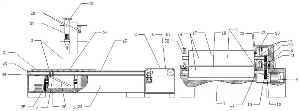
[0046] A fully automatic welding machine control system, comprising a rolling device 1, a transfer assembly 2 arranged at one end of the rolling device 1, and a tank body welding device 3 arranged at the other end of the transfer assembly 2; the rolling device 1 is provided with The drum assembly 4, the transmission assembly 2 is provided with a transmission belt 5 on the upper end surface, the tank body welding device 3 has a slide assembly 26, and the center axis of the drum assembly 4, transmission belt 5, and slide assembly 26 along the length direction On the same straight line, the end of the drum assembly 4 is in close contact with one end of the transmission belt 5, and the other end of the transmission belt 5 is in close contact with one end of the slide assembly 26; The devices are connected in sequence, and the metal plate is sequentially processed by the rolling device, the transfer assembly, and the tank welding device to complete the tank body processing at one ti...

Embodiment 2

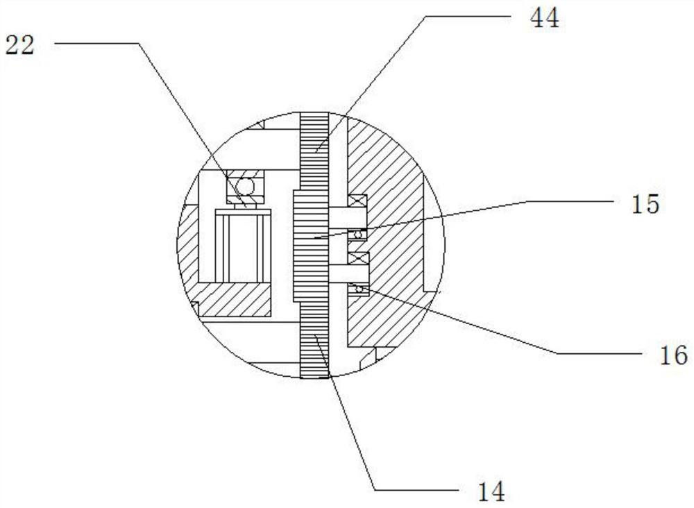
[0048]On the basis of Embodiment 1, the rolling device 1 includes a machine tool body 7, a transmission assembly 8 arranged at one end of the body 7, and the roller assembly 4 is arranged above the body 7; the transmission assembly 8 includes a power motor 9, The gear assembly 10 meshingly connected with the power motor 9, the first rotating main shaft 43 connected with the drum assembly 4, and the second rotating main shaft 11, the first rotating main shaft 43 is provided with a hydraulic lift assembly 12, and the gear assembly 10 includes an outer casing The power gear 13 on the main shaft of the power motor 9, the first transmission gear 14 meshed with the power gear 13, the transmission gear set 15 meshed with the first transmission gear 14, and the second transmission gear 44 meshed with the transmission gear set 15 , the second transmission gear 44 and the first transmission gear 14 are fixedly connected with the first rotating main shaft 43 and the second rotating main s...

Embodiment 3

[0050] On the basis of Embodiment 2, the transmission gear set 15 is hinged with the main body through the rotating main shaft 16 fixedly connected to the center of the transmission gear set 15, and the first rotating main shaft 43 is provided with a bearing on the outer sleeve of the hinged end of the main body, so The above-mentioned bearing is fixedly connected with the body; by setting two meshing gears in the transmission gear set, the power transmission to the first transmission gear is realized and at the same time, the rotation direction of the second transmission gear is opposite to that of the first transmission gear, so that the metal plate enters the first transmission gear. The metal plate behind the gap between the roller and the second roller can enter between the first roller and the second roller under the action of the friction between the first roller and the second roller, and wrap around the outer wall of the first roller to form a Cylindrical.


PUM


Abstract

The invention discloses a full-automatic welding machine control system, and belongs to the technical field of manufacturing tanks. The invention aims to provide a rapid machining system for realizingtank forming and welding. According to the technical scheme, the system involves a rolling device, a delivering assembly arranged at one end of the rolling device and a tank body welding device arranged at the other end of the delivering assembly; and the rolling device is internally provided with a roller assembly, a transmission belt is arranged on the upper end surface of the delivering assembly, the tank body welding device is provided with a sliding plate assembly, the roller assembly, the transmission belt and the sliding plate assembly are arranged on the same straight line along the central axis in the length direction, the end of the roller assembly is tightly attached to one end of the transmission belt, and the other end of the transmission belt is tightly attached to one end of the sliding plate assembly. According to the full-automatic welding machine control system, the rapid machining of the tank forming and the welding is realized, and the good machining efficiency isachieved.

Description

technical field [0001] The invention belongs to the technical field of can making, and in particular relates to a fully automatic welding machine control system. Background technique [0002] Cylindrical tank processing requires a variety of processing procedures, including the most important can processing and welding processing. During the production process, the welding workload is very heavy, and the weld seam has certain requirements. Automatic welding is suitable. The existing automatic welding machines are large in size, complex in structure, and high in purchase and use costs, which are difficult for small and medium-sized enterprises to bear, and it is difficult to ensure welding quality and improve work efficiency. It is very difficult to connect the tank body and the head. It is difficult, because the processed can body is round, and if it is made into an oval can, it is very difficult to shape. Moreover, the existing tank body processing procedure is a conventio...

Claims


Application Information

Patent Timeline
Patent Type & Authority Patents(China)
IPC IPC(8): B23P23/00B23K31/02B23K37/02
CPCB23K31/02B23K37/0211B23P23/00
Inventor 田仲华
Owner 成都市昶泰智能设备有限公司
Why Eureka
Try Eureka