Double-frequency differential band-pass filter based on branch load resonator

A resonator and filter technology, applied in the microwave and radio frequency fields, can solve the problems of low selectivity, the center frequency of the filter cannot be adjusted independently, and the insertion loss is large, so as to achieve enhanced flexibility and convenience, and good common mode rejection characteristics. , the effect of reducing insertion loss

Active Publication Date: 2019-11-12
XIDIAN UNIV
View PDF10 Cites 9 Cited by
  • Summary
  • Abstract
  • Description
  • Claims
  • Application Information

AI Technical Summary

Problems solved by technology

In 2015, Li Yang and other scholars published a paper "Balanced Dual-Band Bandpass Filter With Multiple Transmission Zeros Using Doubly Short-Ended Resonator Coupled Line" in IEEE TRANSACTIONSON MICROWAVE THEORY AND TECHNIQUES journal (VOL.63, NO.7, JULY 2015), proposing A dual-frequency differential bandpass filter based on a double-ended short-circuit resonator is proposed, which realizes three transmission zeros, but the center frequencies of the two passbands of the filter cannot be adjusted independently, and the overall size of the design is large
In 2016, Chu Hui of Nantong University and others invented a dual-frequency differential filter. The authorized announcement number is CN 105762447 B. The multi-layer board is used to achieve a small size, but the structure is complex and the center frequencies of the two passbands of the filter are different. with independent adjustability
In 2018, Jian-Xin Chen and other scholars published a paper "Miniaturized Dual-band Differential Filter Using Dual-mode Dielectric Resonator" in the journal IEEE MICROWAVE AND WIRELESS COMPONENTS LETTERS (VOL.28, NO.8, AUGUST2018), proposing a dual-mode Dielectric Resonator based on The dual-frequency differential filter of the mode dielectric resonator can realize independently adjustable frequency, but there is only one transmission zero point between the two frequency bands, and the out-of-band selectivity of the filter is not good enough
[0003] In summary, based on the shortcomings of the existing differential dual-band filters, such as large structure size, large insertion loss, inability to independently adjust the frequency and bandwidth of the two passbands, and low selectivity, we design a compact, low insertion loss, high Selective, independently adjustable center frequency stub-loaded resonator-based dual-band differential bandpass filter, flexible and practical enough for increasingly complex communication systems

Method used


Image

  • Double-frequency differential band-pass filter based on branch load resonator
  • Double-frequency differential band-pass filter based on branch load resonator
  • Double-frequency differential band-pass filter based on branch load resonator

Examples


Embodiment 1

[0027] With the continuous development of the communication field, the communication system is becoming more and more complex. As an indispensable device in the radio frequency transceiver, the filter becomes particularly important. The performance of the filter is related to the normal operation of the entire communication system. The high-frequency system is particularly complex, which requires the filter to have stronger anti-interference ability, and the differential filter came into being. In recent years, many differential filters have been invented and proposed, but most of them cannot satisfy multi-band, low insertion loss, high selectivity and design flexibility at the same time. In view of these shortcomings, the present invention designs a dual filter based on stub load resonators. frequency difference filter for high selectivity and design flexibility.

[0028] The present invention is a dual-frequency differential bandpass filter based on stub load resonators, see...

Embodiment 2

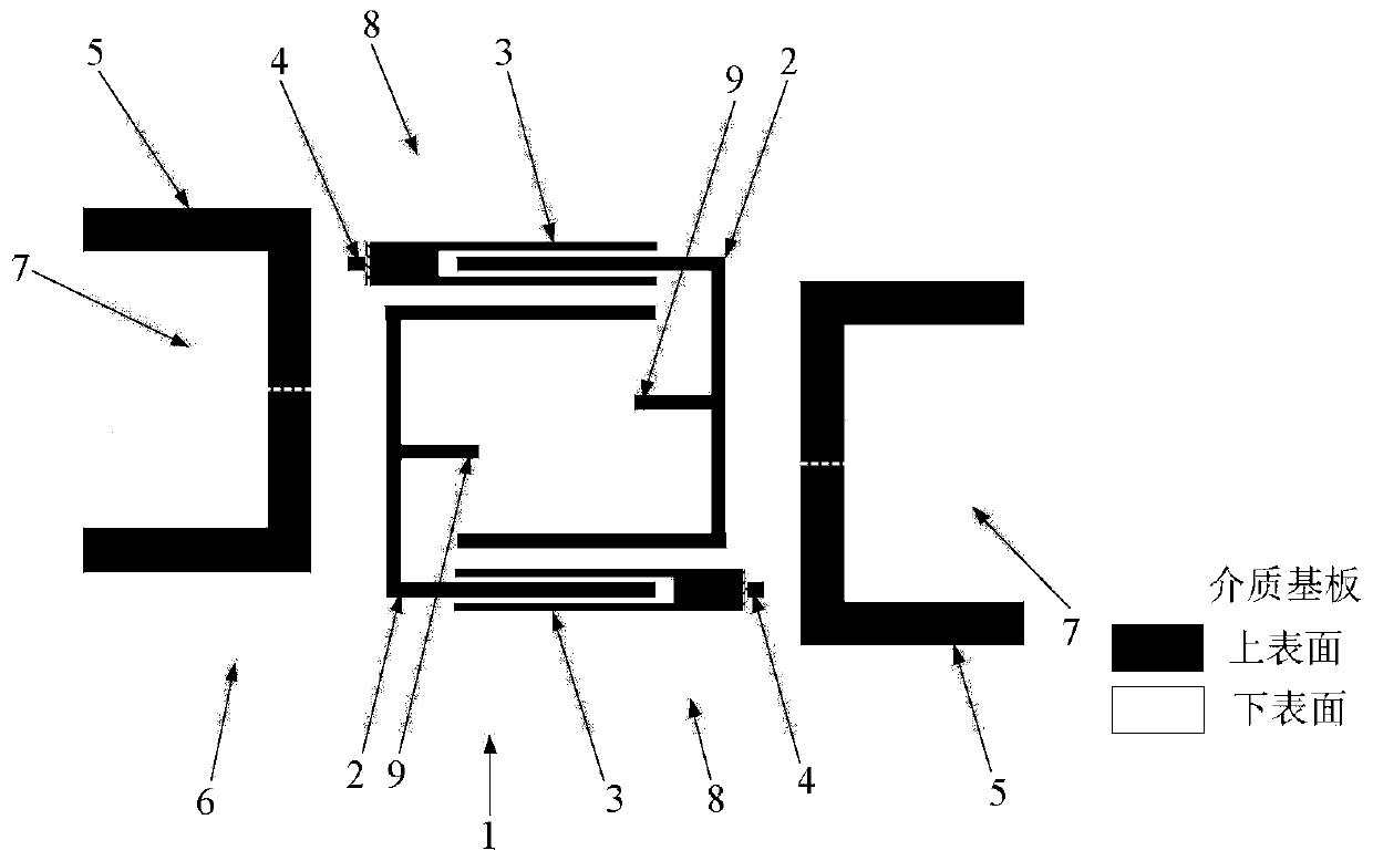
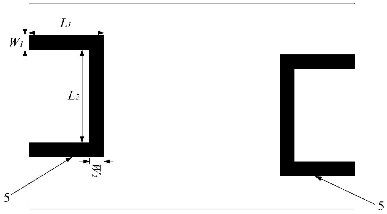
[0036] The overall composition and specific structure of the dual-frequency differential bandpass filter based on stub load resonators are the same as in Embodiment 1, see figure 1 , figure 2 , the opening directions of the two stub load resonators 2 that are symmetrical about the center of the dielectric substrate of the present invention are opposite, see Figure 4 and Figure 5 , that is, the openings of the two E-type stub load resonators 2 face each other, and the coupling mode is quasi-interdigitated coupling. The stubs loaded in the microstrip resonator 2 are either open-circuit stubs or short-circuit stubs, all located at the very center of the C-shaped microstrip line formed by the E-shaped frame. The stub-loaded microstrip resonator 2 includes a C-type microstrip line folded into three sections and a section of stub loaded at the center of the C-type microstrip line. The size of the microstrip resonator is reduced by folding, and multiple frequency bands and It i...

Embodiment 3

[0041] The overall composition and specific structure of the dual-frequency differential bandpass filter based on stub load resonators are the same as those in Embodiment 1-2, see figure 1 , figure 2 , Figure 4 and Figure 5 , the stepped impedance microstrip line 3 of the present invention is formed by connecting a smaller rectangular high-impedance microstrip line and a larger rectangular low-impedance microstrip line, and the end of the high-impedance microstrip line is grounded through a metallized via hole 4 and exceeds The bottom slot line is a quarter of the waveguide wavelength of the microstrip line to achieve a good transition of the differential mode signal from the slot line to the microstrip line. The two microstrip lines are parallel to the long side of the dielectric board 1 , and to achieve a smaller size, the two stepped impedance microstrip lines 3 are symmetrical about the center point of the dielectric substrate.

[0042] see Figure 4 , when the stub...


PUM


Abstract

The invention provides a double-frequency differential band-pass filter based on a branch load resonator. The problems of high insertion loss, low selectivity and inflexible design of a filter are solved. Two opposite quasi-interdigital coupling branch knot load resonators, a stepped impedance microstrip line in three-line interdigital coupling with the quasi-interdigital coupling branch knot loadresonators and U-shaped microstrip lines on the two sides are printed in the middle of the upper surface of a dielectric substrate. The lower surface of the substrate is etched with two linear L-shaped stepped impedance slot lines which rotate 90 degrees counterclockwise. The above structures are all symmetrical about the center of the dielectric substrate. All the structures are symmetrical about the center of the central point of the substrate and are bent by 90 degrees relative to the stepped impedance slot lines, so that the size of the filter is greatly reduced; through quasi-interdigital coupling and three-line interdigital coupling structures, the insertion loss of the filter is reduced and three transmission zeros are formed, so that the selectivity of the filter is enhanced; anda branch knot loaded in the center is in an open circuit mode and a short circuit mode, is independent and adjustable in frequency, meets different requirements, and is used for a radio frequency front end of a wireless communication system.

Description

technical field [0001] The invention belongs to the field of microwave and radio frequency technology, and mainly relates to the structure and design of a bandpass filter, in particular to a dual-frequency differential bandpass filter based on a stub load resonator, which can be applied to a radio frequency front end of a wireless communication system. Background technique [0002] In recent years, with the rapid development of wireless communication technology, filter, as a key frequency selection device, plays an increasingly important role, and its performance often directly affects the quality of the entire communication system. Microstrip bandpass filters are widely used because of their small size, light weight, arbitrary distribution of transmission zeros, and asymmetric suppression characteristics. Since the radio frequency and microwave communication frequency bands are very limited, it is increasingly necessary to expand the high frequency communication frequency b...

Claims


Application Information

Patent Timeline
Patent Type & Authority Applications(China)
IPC IPC(8): H01P1/203
CPCH01P1/20336H01P1/2039
Inventor 魏峰胡雪涵徐乐史小卫
Owner XIDIAN UNIV
Why Eureka
Try Eureka