Imaging system, and method for specifying UV emission location using same

An imaging system, a technique for determining a method, applied in parts of a television system, photometry, photometry using electrical radiation detectors, etc., and can solve problems such as low quantum efficiency

Active Publication Date: 2019-11-12
PANASONIC INTELLECTUAL PROPERTY MANAGEMENT CO LTD
View PDF13 Cites 0 Cited by
  • Summary
  • Abstract
  • Description
  • Claims
  • Application Information

AI Technical Summary

Problems solved by technology

It should be noted that, in the photoelectric conversion element described in Patent Document 1, the quantum efficiency of the short-wavelength side of visible light (400nm) is lower than that of ultraviolet light by two digits, and at a wavelength of 460nm, it is lower than that of ultraviolet light. Five-digit number (refer to the first figure of Patent Document 1)

Method used


Image

  • Imaging system, and method for specifying UV emission location using same
  • Imaging system, and method for specifying UV emission location using same
  • Imaging system, and method for specifying UV emission location using same

Examples


no. 1 approach

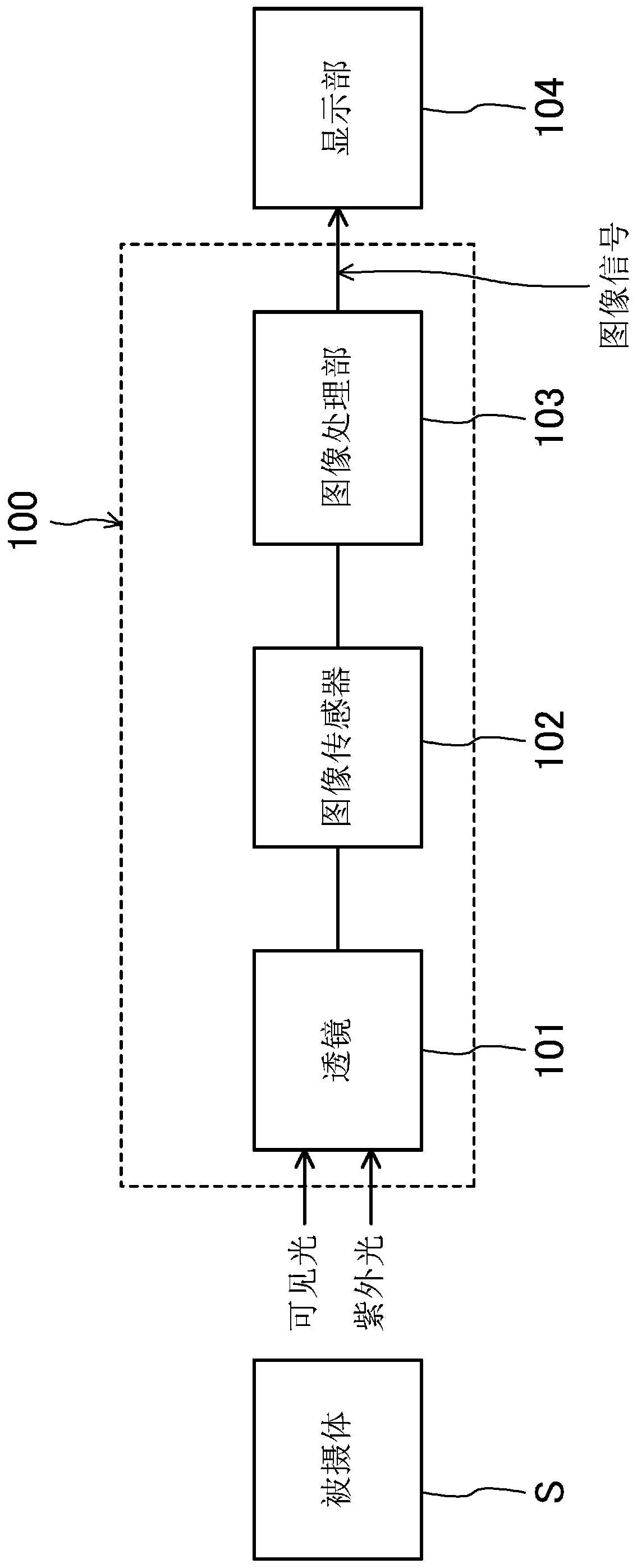
[0030] figure 1 It is a functional block diagram showing the imaging system according to this embodiment. The subject light of the imaging system 100 is ultraviolet light and visible light. It should be noted that, in this specification, the wavelength range of ultraviolet light is above 200nm and below 400nm, and the wavelength range of visible light is above 400nm and below 700nm, but it may also be that the wavelength range of ultraviolet light is above 300nm and below 380nm, and the wavelength range of visible light The region is not less than 400nm and not more than 650nm.

[0031] The imaging system 100 includes a lens (condensing lens) 101 that collects light from a subject S, an image sensor 102 that collects light from a subject S, and an image sensor 102 that receives light collected by the lens 101 and an image processing unit 103. light and photoelectric conversion, the image processing unit 103 processes the output signal from the image sensor 102.

[0032]The ...

no. 2 approach

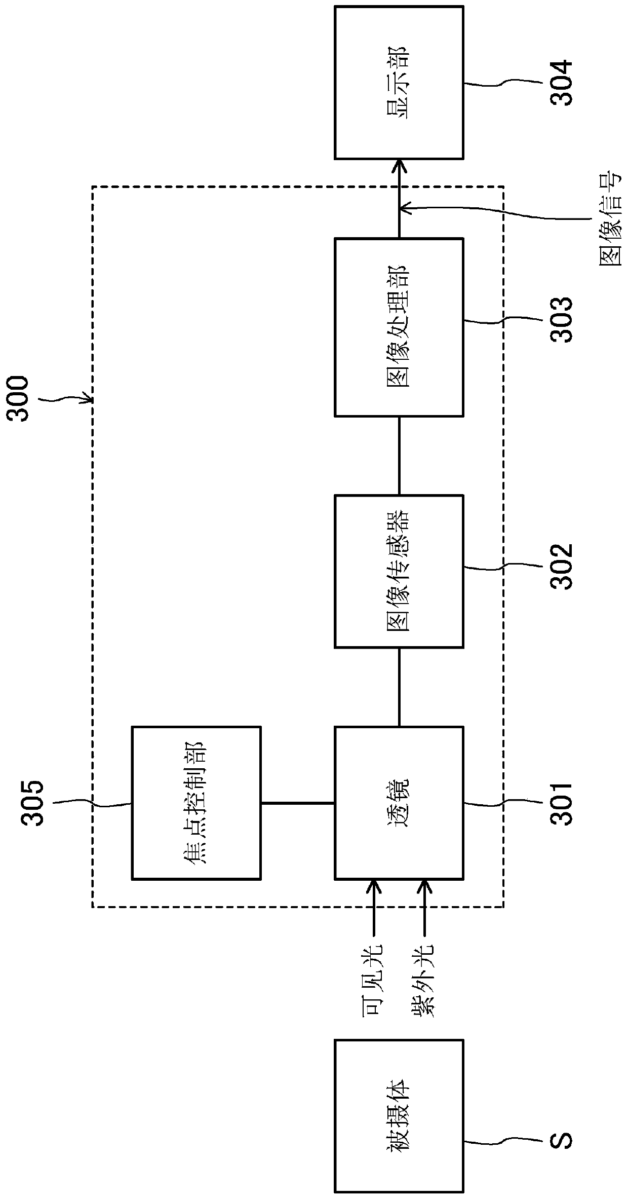
[0051] image 3 It is a functional block diagram showing the imaging system according to this embodiment. The configuration shown in this embodiment differs from the configuration shown in the first embodiment in that a focus control section 305 that controls the position of a lens (condensing lens) 301 and adjusts the focal length is provided. In addition, the lens 301 is a lens not subjected to chromatic aberration correction. It should be noted that, in this embodiment, the subject S is also a high-pressure hydrogen pipeline laid in a hydrogen refueling station or a collection of such pipelines.

[0052] Using the focus control unit 305, the focus of the lens 301 is controlled according to the wavelength of the incident light, thereby enabling more accurate detection of the ultraviolet light-emitting part.

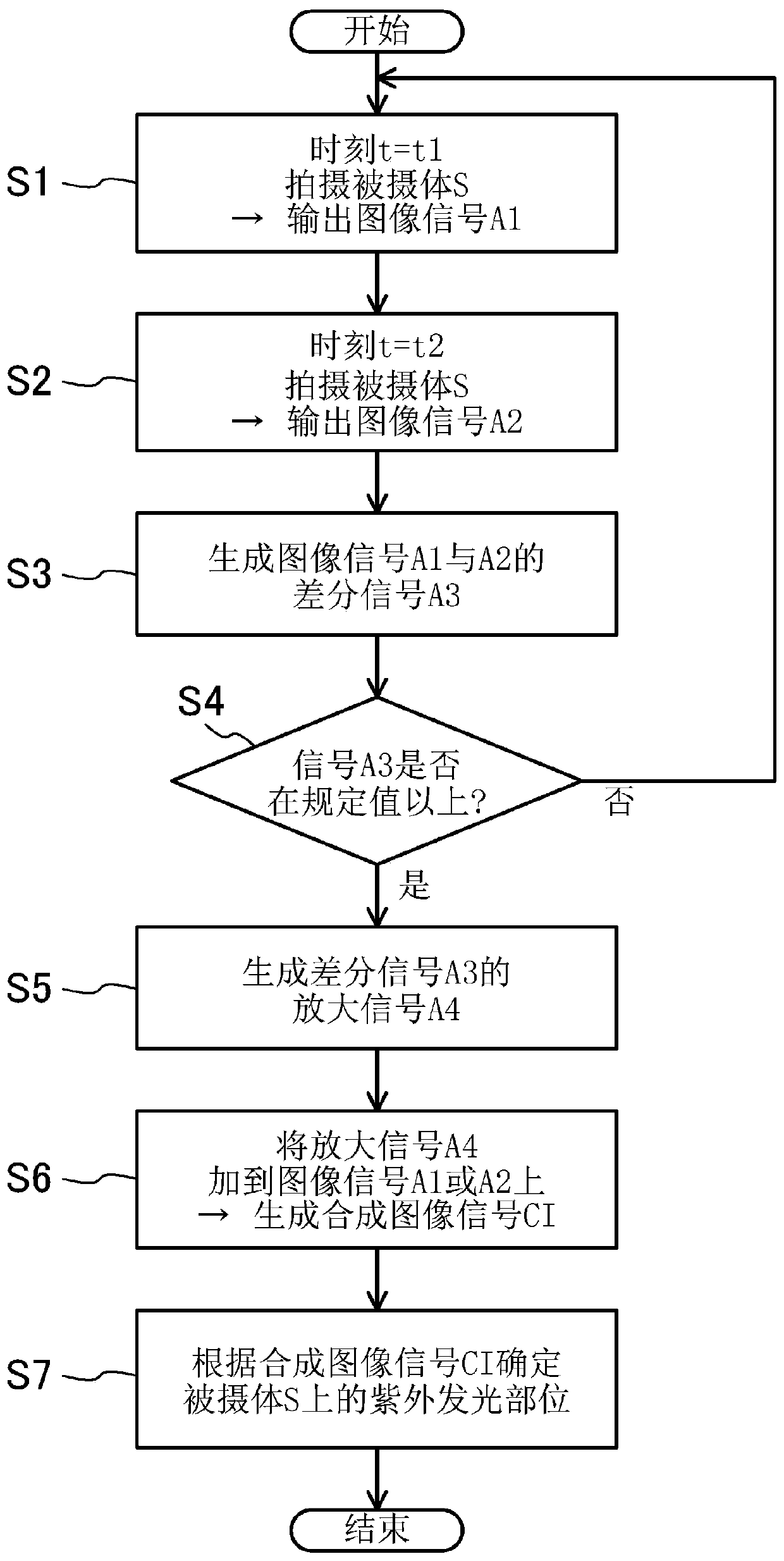
[0053] Figure 4 It is a flow chart showing the identification of the ultraviolet luminescent part according to this embodiment.

[0054] First, the focus control u...


PUM


Abstract

An imaging system (100) comprises an image sensor (102) that has light-receiving sensitivity with respect to UV light and visible light, a lens (101) for concentrating light from a subject S onto theimage sensor, and an image processing unit (103) for processing an image signal outputted from the image sensor (102). The image processing unit (103) acquires the difference between an image signal (A1) and an image signal (A2) that are outputted from the image sensor (101) at times (t1) and (t2), respectively. If a difference signal (A3) is equal to or greater than a prescribed value, it is determined that the light from the subject S includes UV light, and an image signal CI is generated on the basis of the difference signal (A3).

Description

technical field [0001] The invention relates to an imaging system and a method for determining an ultraviolet luminous part using the imaging system. The imaging system can photograph weak ultraviolet light outdoors or in an illumination environment and determine the weak ultraviolet light emitting part. Background technique [0002] So far, a technique has been proposed that simultaneously captures ultraviolet light with a wavelength of less than 400 nm and relatively weak visible light into an ultraviolet photography device, and detects partial discharge while visually observing the background (for example, refer to Patent Document 1). If the weak ultraviolet light is detected with the naked eye under external light or lighting, the illumination light will be obstructed and the ultraviolet light cannot be seen. Therefore, the weak visible light is also taken in along with the ultraviolet light, and the background is confirmed based on the visible light. It should be noted ...

Claims


Application Information

Patent Timeline
Patent Type & Authority Applications(China)
IPC IPC(8): G01J1/42G01J1/04G02B7/28G03B13/36G03B15/00H04N5/225H04N5/232
CPCG01J1/0411G01J1/0448G01J1/4228G01J1/429G01J3/0208G01J3/0237G01J3/32G01J3/443G01N21/33G01N21/8806
Inventor 冲野徹广濑裕山平征二
Owner PANASONIC INTELLECTUAL PROPERTY MANAGEMENT CO LTD
Why Eureka
Try Eureka