Wave energy absorbing and converting device and power generation system

A conversion device and wave energy technology, applied in ocean energy power generation, engine components, general water supply conservation, etc., can solve the problems of reducing device power generation efficiency, uncontrollable, difficult rectification and inverter, etc., to achieve high utilization rate of wave energy, Strong anti-corrosion ability, the effect of solving electricity demand

Pending Publication Date: 2019-11-15
THE QUARTERMASTER RES INST OF THE GENERAL LOGISTICS DEPT OF THE CPLA
View PDF4 Cites 6 Cited by
  • Summary
  • Abstract
  • Description
  • Claims
  • Application Information

AI Technical Summary

Problems solved by technology

The power generation device solves the problems of complex structure, high manufacturing cost and maintenance cost, and low reliability of long-term operation of the existing wave energy power generation device
[0009] The device is feasible in principle, but there are problems in actual operation: since the device is designed with a resistance disc underwater, according to the design plan, the buoyancy of the resistance disc should be equal to gravity to ensure that the resistance disc is suspended in the movement range In the middle, but this is only an ideal state. In fact, it is impossible to create a resistance disc whose buoyancy is equal to gravity. Moreover, even if the buoyancy of the resistance disc is equal to gravity, the underwater position of the resistance disc is uncontrollable
Therefore, in reality, the resistance disc in the water will always have a tendency to move up or down due to its own gravity or buoyancy. The resistance disc will not be in the middle of the design, and will automatically move to one end of the movement range, so When waves drive the floating body to move up and down, the resistance plate will inevitably contact and collide with the limit structure or the lower end of the piston cylinder in each movement cycle. This kind of contact will cause the piston and cylinder to lose relative motion for a period of time and cannot absorb The energy of the waves, loses the effect of capturing wave energy
In the actual operation experiment, the applicant found that each wave movement cycle is about 7 seconds, and the time for the resistance plate to touch the limit structure and lose relative motion is about 3 seconds, which causes the generator to stop repeatedly. Turning and starting, greatly reducing the power generation efficiency of the device
According to the research of the applicant, compared with the theoretical design state, the efficiency of this situation drops by about 80%. The measured voltage output diagram is as follows: image 3 As shown, it can be seen from the figure that the output voltage of the device is from 0 to 648.2V, which is intermittent and extremely discontinuous, and it is difficult to perform rectification and inversion. application

Method used


Image

  • Wave energy absorbing and converting device and power generation system
  • Wave energy absorbing and converting device and power generation system
  • Wave energy absorbing and converting device and power generation system

Examples


Embodiment 1

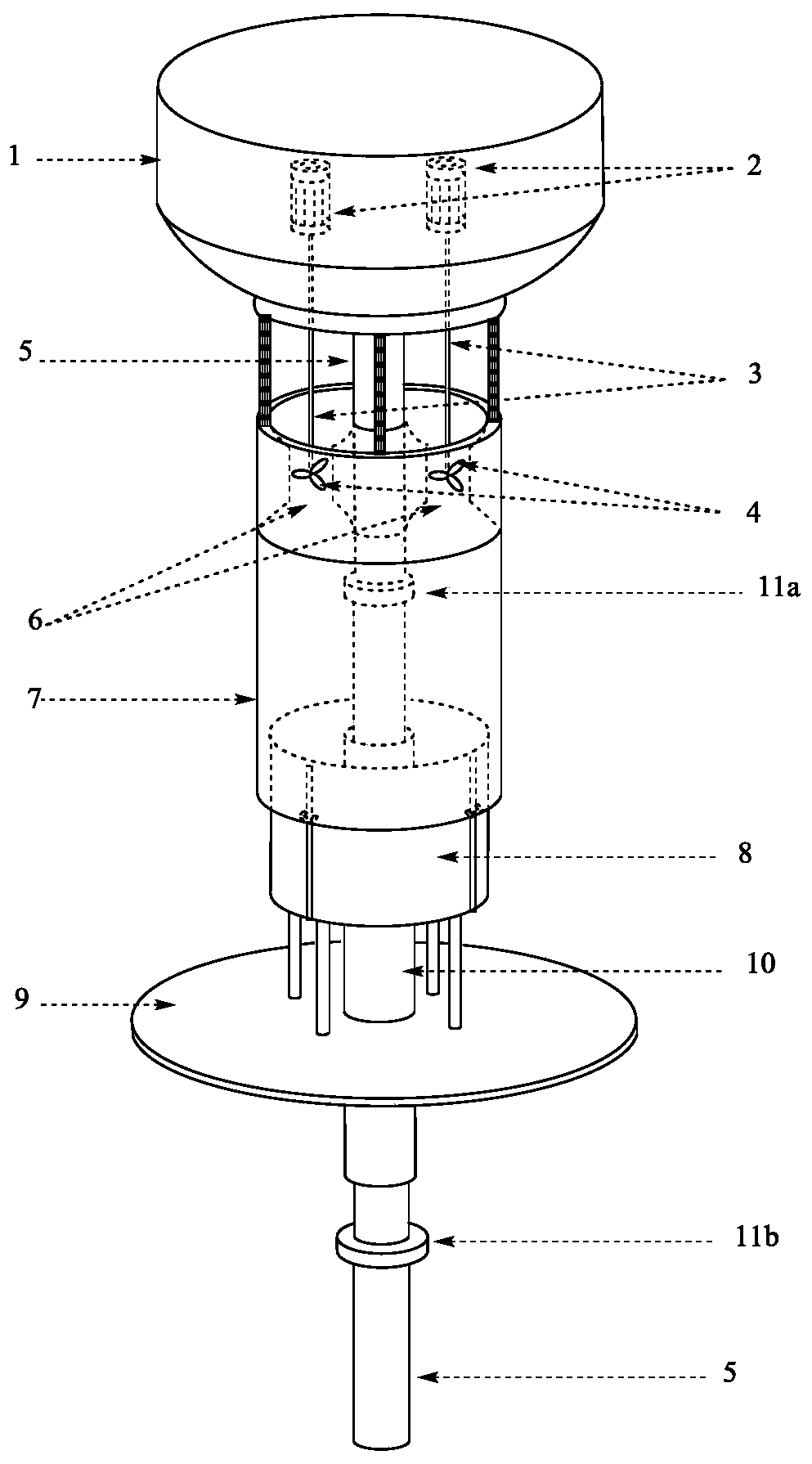
[0038] see Figure 5 , In this embodiment, the wave energy absorption and conversion device includes components such as a buoyant body 1, a resistance disc 9, a guide shaft 5, and a counterbalance mechanism. The guide shaft 5 is connected to the bottom of the floating body 1, and the guide shaft 5 vertically passes through the center of the resistance disc 9, and the resistance disc can slide freely on the guide shaft 5. Limiting structures 11a and 11b are provided on the upper and lower parts of the guide shaft 5, and the movement range of the resistance disc 9 is limited between the two limiting structures 11a and 11b. When the floating body 1 is under the action of waves, it drives the guide shaft 5 to move up and down together, so as to generate relative motion with the resistance plate 9, and output mechanical kinetic energy to the power generation mechanism 13 (the part shown by the dotted line in the figure, it should be noted that this is a schematic Sexual representa...

Embodiment 2

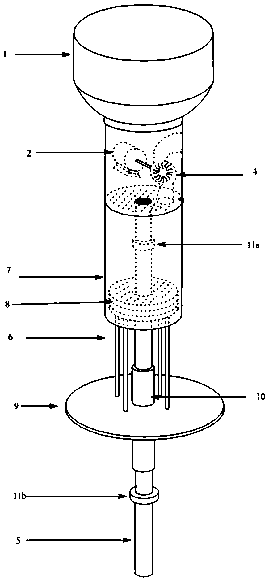
[0042] Combining the structure of embodiment 1 with the piston pressurized water turbine power generation system, a specific wave energy power generation system can be obtained, such as Figure 7 shown. The piston pressurized water turbine power generation device of the system has a generator 2, a water turbine 4, a piston pressurization device and the like. Specifically, the generator 2 is installed in the floating body 1 , and the water turbine 4 and the piston supercharging device are installed below the floating body 1 .

[0043] The piston pressurization device of the system includes a piston 8, a piston sleeve 7 and the like. The piston sleeve 7 is connected to the bottom of the floating body 1, and there is an open water flow channel 6 on its top, through which seawater can enter the cylinder body. The water turbine 4 is located in the water flow channel 6 on the top of the piston sleeve 7, and is connected with the generator 2 in the floating body 1 through its energ...

Embodiment 3

[0049] see Image 6 , this embodiment is aimed at the situation that the sum of the buoyancy of the resistance disc 9 plus its load piston 8 is about less than the sum of the gravity. At this time, it is necessary to configure the buoyancy tank 14b below the resistance disc 9 to counteract the downward movement of the resistance disc. Case 14b connects and draws below the resistance disc 9 with a soft chain, and under the effect of the downward traction of the soft chain, the buoyancy tank 14b is suspended below the resistance disc 9 . The length of this flexible chain will make buoyancy tank 14b be in the middle position of resistance disc 9 movement intervals. When the resistance disc 9 moves from the upper end of its motion range to the middle area, it is combined with the buoyancy tank 14b. If there is no external force, the combined body will stay at the initial combined position. Under the action of external force, the combined body can continue to move downward togethe...


PUM


Abstract

The invention discloses a wave energy absorbing and converting device and a power generation system. The device comprises a floating body, a guide shaft, a resistance disc and a counter mechanism, wherein the counter mechanism is arranged at an motion interval of the resistance disc; the guide shaft is connected with the bottom of the floating body, the resistance disc relatively movably sleeves the guide shaft; counter force of the counter mechanism is opposite to the natural motion direction of the resistance disc so that the resistance disc can remain a relatively stationary state in waterunder own resistance effects and the cooperation of the counter mechanism, then the resistance disc, within a wave height range designed by the device, does not make contact with a limiting structure,a floating body and the like whether in the upper portion or the lower portion. When the floating body drives the guide shaft to move up and down under action of waves, relative motion is generated between the floating body and the resistance disc so as to output kinetic energy; and the kinetic energy is received and converted by a power generation device, and namely outputting electric energy. According to the wave energy absorbing and converting device and the power generation system, simple structure improvement is utilized, so that the wave energy utilization rate is significantly improved, thus reducing power generation cost of wave energy as well as solving the problem of power demands of offshore remote islands and reefs for power supply and seawater desalination.

Description

technical field [0001] The invention relates to a power generation device, in particular to wave energy power generation technology. Background technique [0002] At present, the following methods are commonly used in wave energy generation devices: [0003] 1. Convert wave energy into hydraulic energy, drive the turbine connected to the generator to rotate, and then make the generator rotate to generate electricity. For example, the water snake wave energy generation equipment of Scotland Pelamis Wave Energy Company and the OPT wave energy generation device of American Ocean Power Technology (OPT) Company. However, the design of the wave power generation device using this structure is relatively complicated, the cost is high and the maintenance cost is high, and it still has no cost advantage compared with the current dominant thermal power generation and hydropower generation. [0004] 2. Convert wave energy into flowing compressed air, drive the steam turbine to rotate,...

Claims


Application Information

Patent Timeline
Patent Type & Authority Applications(China)
IPC IPC(8): F03B13/00F03B13/18
CPCF03B13/00F03B13/1875Y02A20/144Y02E10/30
Inventor 王维俊李滨
Owner THE QUARTERMASTER RES INST OF THE GENERAL LOGISTICS DEPT OF THE CPLA
Why Eureka
Try Eureka