Tracking and controlling system of maximum wave energy of wave energy

A technology of tracking control and wave energy, which is applied in the direction of ocean energy power generation, electric vehicles, electrical components, etc., can solve the problems of low power generation efficiency, low energy collection efficiency, and unsuitable application environment, so as to increase power generation efficiency and improve battery life The effect of ability, good environmental adaptability

Active Publication Date: 2019-11-15
DALIAN MARITIME UNIVERSITY
View PDF6 Cites 4 Cited by
  • Summary
  • Abstract
  • Description
  • Claims
  • Application Information

AI Technical Summary

Problems solved by technology

First of all, most of the small wave energy harvesting devices currently appearing are three-stage conversion processes, that is, using mechanical structures to convert the up and down motion of waves into the rotational motion of generators. Due to the existence of intermediate conversion devices, the energy collection efficiency is low
Secondly, most of the current wave energy generation systems for navigation lights are autonomous systems, which cannot achieve maximum wave energy tracking according to changes in water areas
[0003] At present, there are many offshore equipment, such as buoy lights, water detectors, etc., but most of them have energy supply problems, that is, charging multiple times at one time or replacing the power supply, resulting in waste of human and material resources. At present, there have been various energy supplements for buoy lights Solutions, such as the use of solar energy, wind energy, etc., but solar energy is limited by the sun, climate, etc., and th

Method used


Image

  • Tracking and controlling system of maximum wave energy of wave energy
  • Tracking and controlling system of maximum wave energy of wave energy
  • Tracking and controlling system of maximum wave energy of wave energy

Examples


Embodiment 1

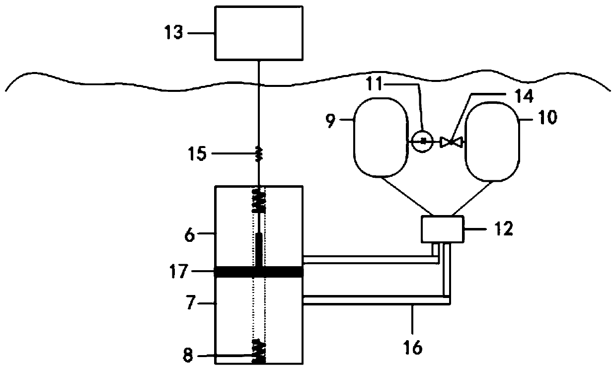
[0037] The controllable hydraulic system 2 uses hydraulic oil as the working medium for transferring energy, and the system is composed of a signal control part and a hydraulic power part. The signal control part transmits the sensor signal to the central controller through the vertical speed of the wave measured by the sensor, and the actuator is the speed of the hydraulic pump 11 and the state of the electromagnetic control valve 12; the hydraulic power part provides For the hydraulic pump 11 and the electromagnetic control valve 12, the hydraulic pump 11 controls the flow rate of the hydraulic oil, and the electromagnetic control valve controls the flow direction of the hydraulic oil 12. After the supplement of the hydraulic system, the movement of the stator is consistent with the up and down motion of the wave energy, forming resonance to achieve the maximum absorption of wave energy. Of course, the controllable hydraulic system 2 does not change in real time. Set differen...

Embodiment 2

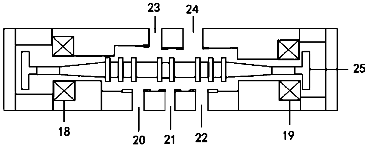
[0048] The electromagnetic control valve 12 includes a first electromagnetic coil 18, a second electromagnetic coil 19, a first liquid discharge port 20, a second liquid discharge port 22, a pressure port 21, a first port 23, a second port 24 and a spool 25; The port 21 is a machine port, the first port 23 is connected to the upper hydraulic chamber 6, the second port 24 is connected to the lower hydraulic chamber 7, the first liquid discharge port 20 is connected to the first hydraulic cylinder 9, and the second liquid discharge port 22 is connected to the second hydraulic cylinder 10. Controlling the energization of the first electromagnetic coil 18 and the second electromagnetic coil 19 through the controllable hydraulic system, so as to control the flow direction of the hydraulic oil, and then push the piston 17 to move up and down.

[0049] The specific implementation is as follows. When the piston 17 intends to move downward, the first electromagnetic coil 18 is energized...

Embodiment 3

[0052] The linear generator system 3 is a cylindrical permanent magnet synchronous linear motor with 12 slots and 11 poles, which includes a mover, a stator, a permanent magnet and a three-phase coil. The permanent magnet is attached to the surface of the mover, and the three-phase coil is embedded in the stator. in the slot. When the mover reciprocates up and down with the waves, it will move relative to the stator, thereby generating an induced electromotive force at the output end of the stator winding, realizing the conversion of wave energy into electrical energy. The cylindrical permanent magnet synchronous linear motor with 12 slots and 11 poles has a simple structure, which can realize the first-stage conversion of wave energy to electric energy, and effectively improve the conversion efficiency of wave energy.


PUM


Abstract

The invention provides a tracking and controlling system of maximum wave energy of wave energy, belongs to the field of new energy sources, and aims at solving the existing problem of water accumulation existing in the wave energy. The tracking and controlling system comprises a vibrating floater system, a controllable hydraulic system, a linear generator system and a mooring system, wherein the controllable hydraulic system is connected with the linear generator system, and the controllable hydraulic system and the linear generator system are both installed on the vibrating floater system; and the vibrating floater system is connected with the mooring system and enables the mooring system to be connected with the seabed. According to the tracking and controlling system, the linear generator system is adopted as a wave energy core collecting mechanism to directly transform mechanical energy of the up-and-down movement of waves into electric energy, so that the wave energy collecting efficiency is greatly improved; meanwhile, regarding changeable marine environment, irregular waves and other factors, a hydraulic system is designed to realize the maximum wave energy tracking and optimize a wave energy collecting system; and the tracking and controlling system has the advantages of strong environmental adaptability, high wave energy collection efficiency and the like, can realizeall-weather wave energy collection, and provides possibility for developing and efficiently utilizing the wave energy to generate power.

Description

technical field [0001] The present invention relates to the field of new energy technology, in particular to a maximum wave energy tracking control system for wave energy. Background technique [0002] As a supply device for offshore equipment, the wave energy power generation system is mainly used to provide electrical energy for marine beacon lights, shallow water detection underwater vehicles and other equipment. At present, various small-scale wave energy generating devices have appeared to be used for power supply such as buoy lights on the sea. First of all, most of the small wave energy harvesting devices currently appearing are three-stage conversion processes, that is, using mechanical structures to convert the up and down motion of waves into the rotational motion of generators. Due to the existence of intermediate conversion devices, the energy collection efficiency is low. Secondly, most of the current wave energy generation systems for navigation lights are aut...

Claims


Application Information

Patent Timeline
IPC IPC(8): F03B13/20F03B11/00H02J7/35
CPCF03B11/00F03B11/008F03B13/20H02J7/35Y02E10/20Y02E10/30
Inventor 王宁贾玉森付水张耀中李春艳王泊桦
Owner DALIAN MARITIME UNIVERSITY
Why Eureka
Try Eureka