A capacitive humidity sensor based on an "arch" structure and its preparation method and application

A humidity sensor, capacitive technology, applied in material capacitance, instruments, scientific instruments, etc., can solve the problem of inability to precisely control the morphology and size of polymers, and achieve short response/recovery time, controllable morphology, and simple process. Effect

Active Publication Date: 2022-03-11
UNIV OF JINAN
View PDF0 Cites 0 Cited by
  • Summary
  • Abstract
  • Description
  • Claims
  • Application Information

AI Technical Summary

Problems solved by technology

This method has the advantages of easy access to templates and large-area production, but it cannot precisely control the shape and size of polymers, which is greatly limited.

Method used


Image

  • A capacitive humidity sensor based on an "arch" structure and its preparation method and application
  • A capacitive humidity sensor based on an "arch" structure and its preparation method and application
  • A capacitive humidity sensor based on an "arch" structure and its preparation method and application

Examples


Embodiment 1

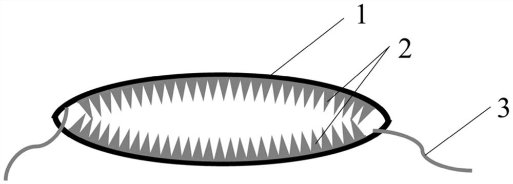
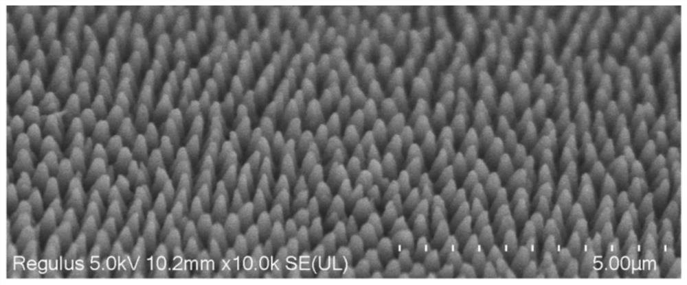
[0052] refer to figure 1 , a capacitive humidity sensor based on an "arch" structure, including an electrode 1, a dielectric layer 2 and a wire 3, the electrode 1 includes a top electrode and a bottom electrode, both of which are "arch" structures, and the top electrode The dielectric layer 2 of the arrayed nanocone structure is arranged on the bottom electrode, and the cone tip faces away from the surface of the electrode where it is located. The top electrode and the bottom electrode are assembled to form a ring structure, and the dielectric layers on the two electrodes are located in the ring The inner side of the structure; wires 3 are arranged on the top electrode and the bottom electrode.

Embodiment 2

[0054] A capacitive humidity sensor based on an "arch" structure, the same as in Embodiment 1, the difference is that: the top electrode and the bottom electrode are both composed of a flexible PET substrate and ITO attached to the substrate, that is, phthalic acid Glycol ester-indium tin oxide (PET-ITO). The material of the dielectric layer is polyvinylidene fluoride-trifluoroethylene (P(VDF-TrFE)).

Embodiment 3

[0056] A method for preparing a capacitive humidity sensor based on an "arch" structure, comprising the steps of:

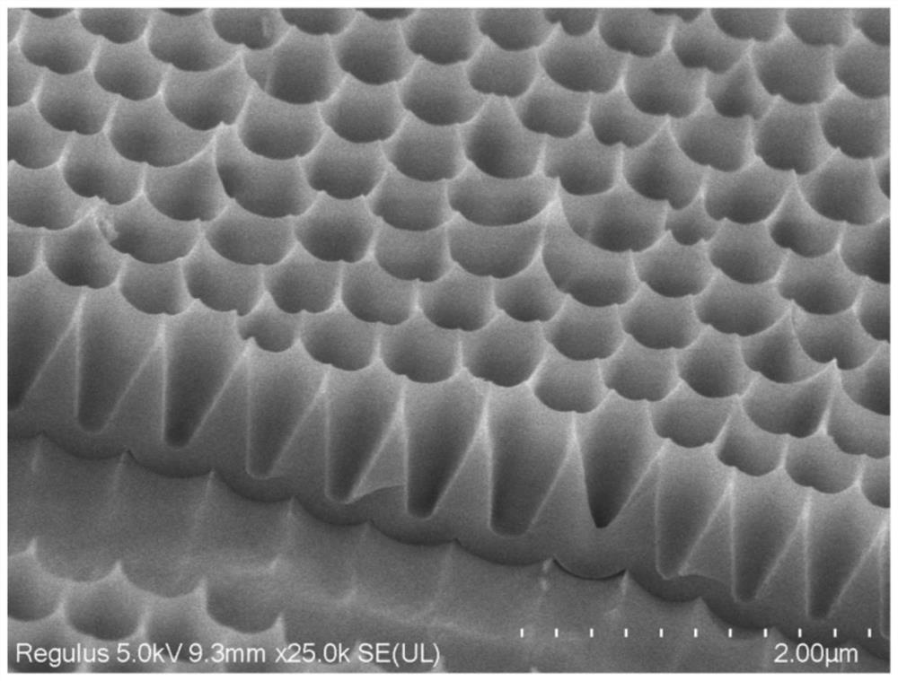
[0057] (1) Preparation of porous tapered nanopore template AAO, the specific steps are as follows:

[0058] (1-1) Soak the aluminum sheet in acetone, ethanol, and deionized water in sequence, ultrasonically clean each for 15 minutes, then move to a plasma-enhanced chemical vapor deposition (PECVD) device, anneal at 600°C for 10 hours, and then place the aluminum sheet on a single Surface electropolishing;

[0059] (1-2) Embossing the surface of the electropolished aluminum sheet through a silicon mold with a honeycomb nanocone structure to produce a nano-depression array;

[0060] (1-3) With the aluminum sheet obtained in step (1-2) as the anode, the lead block as the cathode, and 0.4mol / L oxalic acid as the electrolyte, a direct current (DC) voltage of 215V is used, and the reaction time is 2h. orderly oxide film, soak the aluminum sheet after the first oxidat...


PUM

PropertyMeasurementUnit
diameteraaaaaaaaaa
heightaaaaaaaaaa
diameteraaaaaaaaaa

Abstract

The invention relates to the technical field of humidity sensors, in particular to a capacitive humidity sensor based on an "arch" structure, its preparation method and application. The humidity sensor includes: a top electrode and a bottom electrode, both of which have an "arch" structure; a medium layer, the top electrode and the bottom electrode are all provided with a medium layer of an arrayed nanocone structure, and the cone points are facing away from it The surface of the electrode where it is located; wires, wires are arranged on the top electrode and the bottom electrode; the top electrode and the bottom electrode are assembled to form a ring structure, and the dielectric layers on the two electrodes are located inside the ring structure. Compared with some existing technologies, the present invention proposes a high-performance capacitive humidity sensor with high sensitivity, short response / recovery time, good repeatability and its low cost, simple process, controllable shape and large-scale Production method of preparation.

Description

technical field [0001] The invention relates to the technical field of humidity sensors, in particular to a capacitive humidity sensor based on an "arch" structure, its preparation method and application. Background technique [0002] The information disclosed in the Background of the Invention is only intended to increase the understanding of the general background of the invention, and is not necessarily to be taken as an acknowledgment or any form of suggestion that the information constitutes the prior art that is already known to those skilled in the art. [0003] Humidity sensors are widely used in many fields such as industry, meteorological monitoring, medicine and agriculture. According to the influence of humidity on the electrical performance of the sensor, humidity sensors are roughly divided into two categories: resistive and capacitive. Although the resistive humidity sensor has the advantages of low cost and simple structure, its logarithmic response to humid...

Claims


Application Information

Patent Timeline
Patent Type & Authority Patents(China)
IPC IPC(8): G01N27/22
CPCG01N27/223
Inventor 李阳牛闳森孙英明高嵩岳文静
Owner UNIV OF JINAN
Why Eureka
Try Eureka