
Ultraviolet LED chip and preparation method thereof

A LED chip and ultraviolet technology, which is applied in the direction of electrical components, circuits, semiconductor devices, etc., can solve the problems of poor heat dissipation, discounted brightening effect, failure, etc., and achieve the effect of improving brightness

Active Publication Date: 2019-11-22
XIAMEN SANAN OPTOELECTRONICS CO LTD
View PDF14 Cites 8 Cited by
  • Summary
  • Abstract
  • Description
  • Claims
  • Application Information

AI Technical Summary

Problems solved by technology

As proposed in other published patents, the use of SiO 2 It is a laminated layer, that is, a high and low refraction method to achieve the effect of brightening, but SiO 2 When more Si is doped, its refractive index will become larger, and then stacked with other high-fold film layers, its brightening effect will be greatly reduced
And SiO 2 The thermal conductivity is only 1.4W / m·k, the thicker the film layer, the worse the heat dissipation effect, and the aging process will cause failure due to thermal effects
In addition, SiO 2 As a hydrophilic material, adjusting the ratio of the recipe or increasing the thickness only delays the entry time of water vapor, but cannot essentially avoid the entry of water vapor. This feature makes it weaker in high-humidity aging resistance

Method used


Image

  • Ultraviolet LED chip and preparation method thereof
  • Ultraviolet LED chip and preparation method thereof
  • Ultraviolet LED chip and preparation method thereof

Examples


Embodiment 1

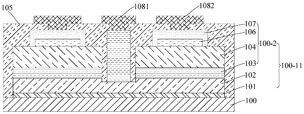
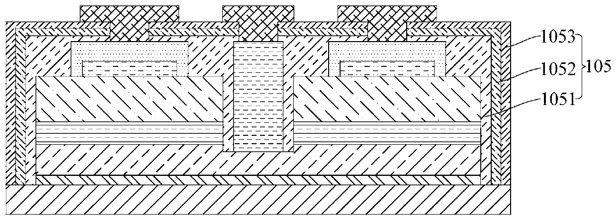
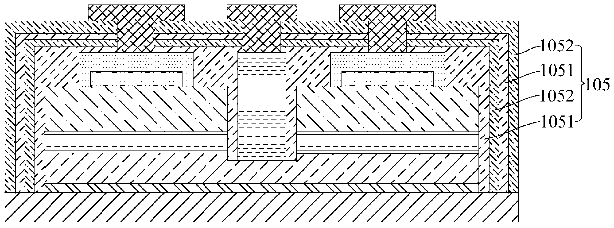
[0065] Such as Figure 1-4 As shown, in this embodiment, the light-emitting epitaxial layer 100-11 is formed above the substrate 100, and the light-emitting epitaxial layer includes a first semiconductor layer 102, an active layer 103, and a first semiconductor layer sequentially formed above the substrate 100. The second semiconductor layer 104 of opposite conductivity type. The above-mentioned first semiconductor layer 102 forms the first mesa 100-1 of the light-emitting epitaxial layer 100-11 (refer to the attached Figure 4 As shown), the active layer 103 and the second semiconductor layer 104 form the second mesa 100-2 of the light emitting epitaxial layer 100-11.

[0066] In a preferred embodiment of this embodiment, the substrate may be a sapphire substrate, the first semiconductor layer 102 may be an N-type semiconductor layer, and the N-type semiconductor layer may include, for example, an AlN / AlGaN superlattice layer, The heavily doped N-type AlGaN layer, the light...

Embodiment 2

[0076] This embodiment also provides a method for preparing an ultraviolet LED chip, such as Figure 4 As shown, the method includes the following steps:

[0077] forming a light-emitting epitaxial layer, sequentially depositing a first semiconductor layer, an active layer, and a second semiconductor layer having a conductivity type opposite to that of the first semiconductor layer, the first semiconductor layer forming a first mesa of the light-emitting epitaxial layer, The active layer and the second semiconductor layer form a second mesa of the light emitting epitaxial layer;

[0078] An insulating protection layer is formed above the light-emitting epitaxial layer, the insulating protection layer covers the surface and side surfaces of the first mesa and the second mesa, and the insulating protection layer includes an insulating layer containing Al.

[0079] The light-emitting epitaxial layer can be formed by methods commonly used in the art. Such as Figure 5 As shown,...


PUM


Abstract

The invention provides an ultraviolet LED chip and a preparation method thereof. The ultraviolet LED chip includes a light emitting epitaxial layer including a first mesa and a second mesa, and an insulating protective layer formed on surfaces and side faces of the first mesa and the second mesa; the insulating protective layer includes an Al-containing insulating layer, and may form a single-layer or multi-layer stacked structure. By adopting the Al-containing insulating protection layer, replacement of Al ions in the epitaxial layer can be reduced, Al ions missing in the epitaxial layer in achip manufacturing process can be effectively compensated, Si doping in the epitaxial layer cannot be affected, the epitaxial layer cannot be damaged, and aging failure of the epitaxial layer is avoided. The absorption rate of the Al-containing insulating protection layer in the ultraviolet band is low, and meanwhile, when the Al-containing insulating layer of a multi-layer structure is formed, an insulating film laminated structure with high and low refractive indexes can be formed, so that the purpose of brightening can be achieved.

Description

technical field [0001] The invention relates to the technical field of semiconductor lighting, in particular to an ultraviolet LED chip and a preparation method thereof. Background technique [0002] LED (light emitting diode, light emitting diode) is a semiconductor device that uses energy released when carriers recombine to form light. Among them, ultraviolet LED (UV LED), especially the huge application value of deep ultraviolet LED has aroused people's high attention and has become a new research hotspot. [0003] The insulating protective layer of UV LED products currently on the market usually uses SiO 2 . During the process of depositing the insulating protective layer, the insulating protective layer not only covers the P-AlGaN and its metal contact layer, but also covers the position of the scribe line and the quantum hydrazine. Therefore, when depositing SiO 2 In the process (whether PECVD or ALD is used), the deposition temperature needs to be above 240°C to a...

Claims


Application Information

Patent Timeline
Patent Type & Authority Applications(China)
IPC IPC(8): H01L33/44H01L33/46H01L33/00
CPCH01L33/44H01L33/46H01L33/0075H01L2933/0025
Inventor 黄敏刘小亮彭康伟林素慧
Owner XIAMEN SANAN OPTOELECTRONICS CO LTD
Learn More