
Sputtering target for transparent conductive film

A technology of transparent conductive film and sputtering target, which is applied in the direction of sputtering coating, conductive layer on insulating carrier, circuit, etc., can solve the problems of high resistance, poor productivity, and low chemical resistance of conductive film, and achieve Effect of low resistivity and high resistivity

Active Publication Date: 2019-12-06
MITSUI MINING & SMELTING CO LTD
View PDF7 Cites 0 Cited by
  • Summary
  • Abstract
  • Description
  • Claims
  • Application Information

AI Technical Summary

Problems solved by technology

However, the chemical resistance of any conductive film is low
[0007] In addition, a large number of high-resistance films have been reported, but the resistance of the target used for the film formation of the film also becomes high
If the resistance of the target is high, sputtering cannot be performed with a DC power supply, and a high-resistance film must be produced with an RF power supply, so productivity is poor

Method used


Image

  • Sputtering target for transparent conductive film

Examples


Embodiment

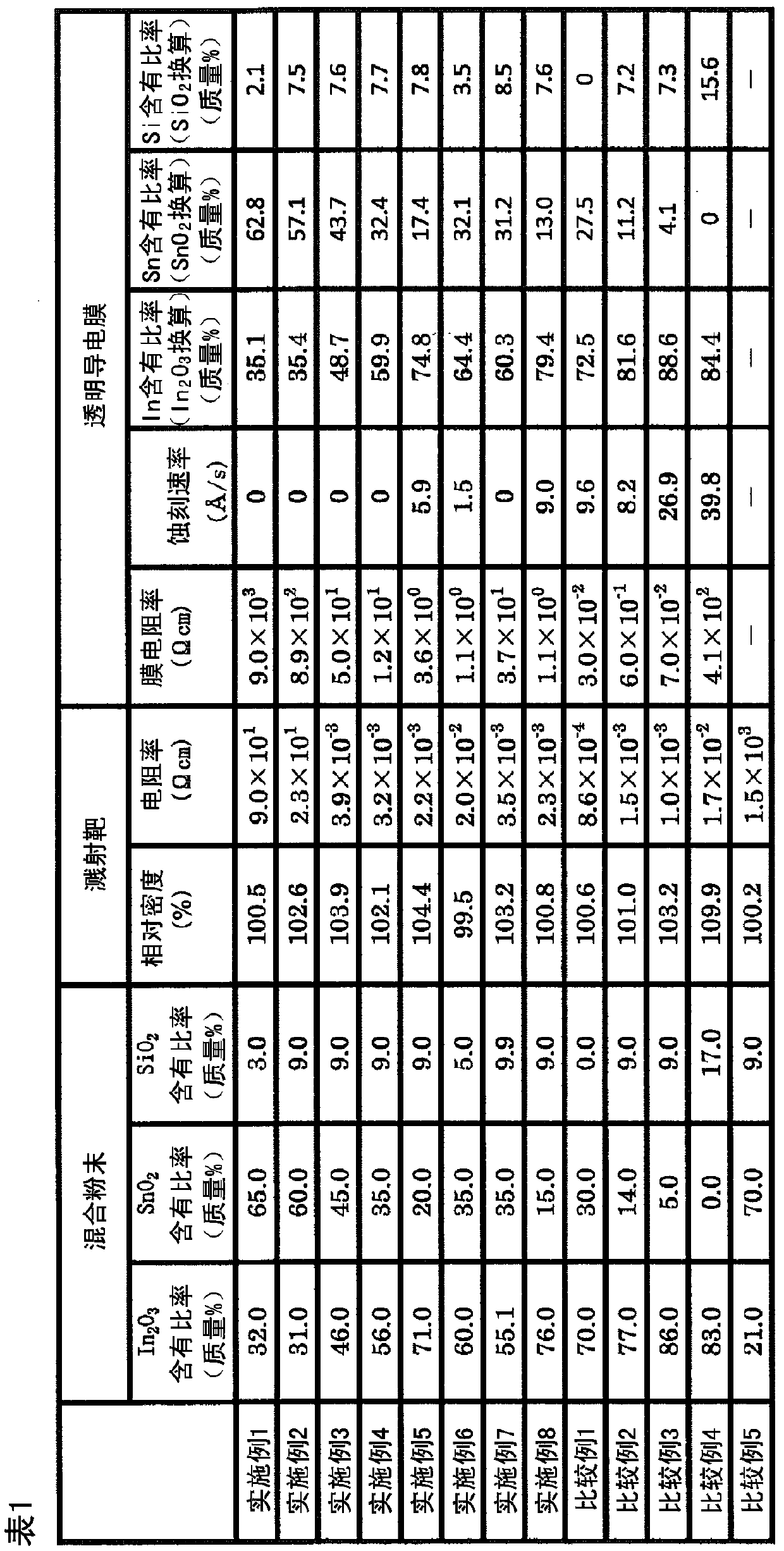
[0051] The measurement methods used in the following Examples and Comparative Examples are shown below.

[0052] 1. The relative density of the target

[0053] The relative density of the sputtering target for a transparent conductive film is measured based on the Archimedes method. Specifically, the mass of the target in the air divided by the volume (the mass of the target in water / the specific gravity of water at the measurement temperature) will be relative to the theoretical density ρ(g / cm) based on the following formula (X) 3 The value of the percentage of) is taken as the relative density (unit: %).

[0054] ρ=((C1 / 100) / ρ1+(C2 / 100) / ρ2+…+(Ci / 100) / ρi) -1 (X)

[0055] (In the formula, C1~Ci respectively represent the content (mass%) of the constituent material of the target, and ρ1~ρi represent the density of each constituent material corresponding to C1~Ci (g / cm 3 ). )

[0056] In the following examples and comparative examples, the substance (raw material) used in the manufactu...


PUM


Abstract

This sputtering target for transparent conductive film comprises an oxide sintered compact having, as constituent elements, In, Sn, Si and O, the content ratio of In being greater than 25.0% by mass but not more than 82.0% by mass in terms of In2O3, the content ratio of Sn being 15.0% by mass to 65.0% by mass in terms of SnO2, and the content ratio of Si being at least 3.0% by mass but less than 10.0% by mass in terms of SiO2. This sputtering target for conductive film has low resistivity, it is possible to perform DC sputtering, and by sputtering it is possible to form a transparent conductive film having high film resistivity and high chemical resistance.

Description

Technical field [0001] The present invention relates to a sputtering target for a transparent conductive film. Specifically, it relates to a sputtering target for a transparent conductive film capable of performing DC sputtering and forming a transparent conductive film with high chemical resistance. Background technique [0002] For the transparent conductive film used in the in-cell type electrostatic capacitance type touch panel, in order to prevent the low frequency noise from hindering the operation of the display, high resistance and high transmittance are required. This is because when the conductive film has low resistance, high frequency signals used for touch sensing are blocked. [0003] This conductive film is usually formed by sputtering a sputtering target. [0004] As a high-transmittance material, ITO is mainly used, but because ITO has a low resistance, it cannot be used as a conductive film for an in-cell capacitive touch panel. [0005] As a technique for obtaining...

Claims


Application Information

Patent Timeline
IPC IPC(8): C23C14/34C04B35/01C04B35/457C23C14/08H01B5/14H01B13/00
CPCC04B35/01C04B35/457C23C14/08C23C14/34H01B5/14H01B13/00C23C14/3414C04B2235/3293
Inventor 矢野智泰儿平寿博立山伸一中村信一郎
Owner MITSUI MINING & SMELTING CO LTD
Learn More