Optical fiber magnetic field sensor and preparation method thereof

A magnetic field sensor, optical fiber technology, applied in the size/direction of the magnetic field, the use of magneto-optical equipment for magnetic field measurement, instruments and other directions, can solve the problem of insufficient sensitivity of the fiber grating magnetic field sensor, and achieve the effect of high fluorescence collection efficiency

Active Publication Date: 2019-12-10
HUAZHONG UNIV OF SCI & TECH
View PDF5 Cites 9 Cited by
  • Summary
  • Abstract
  • Description
  • Claims
  • Application Information

AI Technical Summary

Problems solved by technology

[0008] For the defects of the prior art, the purpose of the present invention is to solve t

Method used


Image

  • Optical fiber magnetic field sensor and preparation method thereof
  • Optical fiber magnetic field sensor and preparation method thereof
  • Optical fiber magnetic field sensor and preparation method thereof

Examples


preparation example Construction

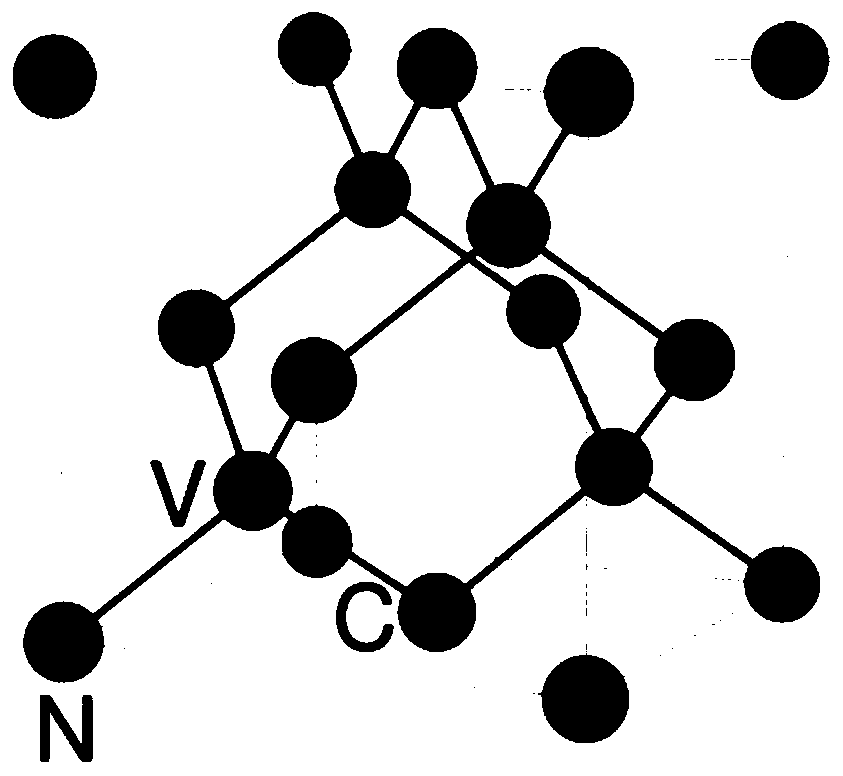
[0042] The preparation process of micro-nano diamond particles has been very mature. Micro-nano diamond particles can be obtained by bombarding the bulk diamond samples containing nitrogen-vacancy centers, or by ionizing the nano-diamond samples without nitrogen-vacancy centers. Implanted to form nitrogen-vacancy centers.

[0043] The optical fiber can be a single-mode optical fiber or a multi-mode optical fiber. The diameter of the single-mode optical fiber is generally about 10 microns, and the diameter of the multi-mode optical fiber is 50 microns to 100 microns. Single mode fiber is recommended.

[0044] The diamond micro-pillars or micro-nano-diamond particles are implanted and fixed from one end of the fiber, and microwaves are applied to the detection end. From the other end, a laser of a specific wavelength (usually 532 nm) can be irradiated, and nitrogen- The fluorescence emitted from the vacancy center can be measured.

[0045] In order to apply microwave pulses, (...

Embodiment 1

[0048] The diamond micro-pillars with a height of 10 microns and a diameter of 4 microns are prepared into an aqueous solution. The concentration of the aqueous solution can be adjusted according to needs. In order to ensure the preparation efficiency, the concentration can be configured to contain an average of 0.01 to 10 diamond micro-pillars per cubic micron. The average diameter and length of the diamond micropillars need to be smaller than the diameter of the fiber core used. In this embodiment, a single-mode optical fiber with a core diameter of 8 microns is selected, one end of the optical fiber is immersed in the configured micropillar solution, and the instrument is used from the other end. Or the device draws out 0.1μL-1μL of gas, and the solution will be drawn into the fiber. Take the fiber out of the solution and dry it.

[0049] From the other end of the fiber, the 532nm laser emitted by the laser is coupled into the fiber with the objective lens, and the fluoresc...

Embodiment 2

[0054] Place diamond micro-pillar powder with a height of 10 microns and a diameter of 4 microns in a beaker, place one end of a single-mode optical fiber with a core diameter of 8 microns close to the powder surface, and extract 0.1 μL-1 μL of gas from the other end using instruments or equipment.

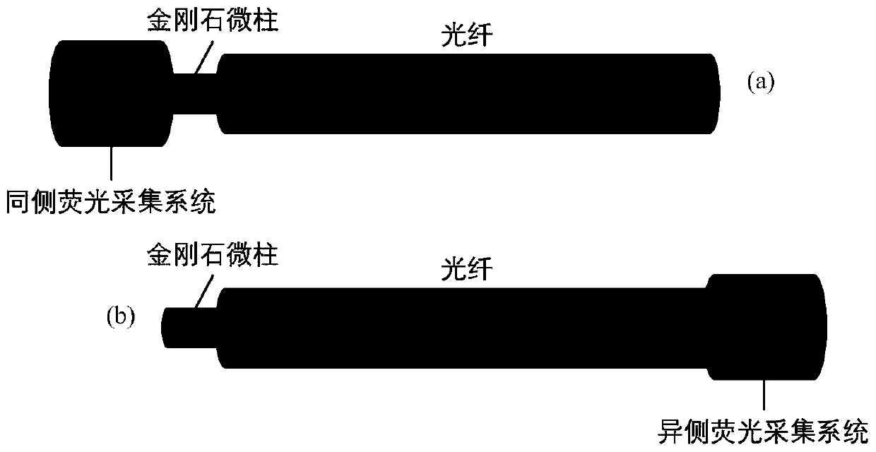
[0055] Implantation Detection: Reference Figure 5 or Image 6 , Figure 5 The structure of coupling diamond micro-pillars or micro-nano diamond particles and optical fibers provided by the present invention is a schematic diagram of realizing magnetic field measurement through microwave wires; Image 6 In order to couple the structure of the optical fiber with the diamond micro-pillars or micro-nano-diamond particles and the surface-etched microwave wire, the microwave wire on the surface of the optical fiber is used to realize the magnetic field measurement, and the microwave can be applied to the optical fiber by implanting the microwave waveguide in the coating layer of the o...


PUM


Abstract

The invention discloses an optical fiber magnetic field sensor and a preparation method thereof. The optical fiber magnetic field sensor comprises an optical fiber and a plurality of diamond micro-columns, the plurality of diamond micro-columns are positioned at one end in the optical fiber; each diamond micro-column contains a nitrogen-vacancy center; when the optical fiber magnetic field sensoris used for measuring a magnetic field, one end, containing the diamond micro-column, of the optical fiber is placed in an environment of the magnetic field to be measured, and laser with a preset wavelength is emitted from the other end of the optical fiber, so that the the nitrogen-vacancy center is excited to emit fluorescence; and steps of transmitting a sweep frequency signal in a preset frequency range to one end, containing the diamond micro-column, of the optical fiber, collecting fluorescence, and determining the size of the magnetic field to be measured by analyzing the change rule of the intensity of the fluorescence along with the frequency of the sweep frequency signal are carried out. According to the invention, more nitrogen-vacancy centers can be integrated at an optical fiber port, the sensitivity is related to the number of the nitrogen-vacancy centers in the sample, and a magnetometer with higher sensitivity can be obtained through the diamond micro-column sample with higher nitrogen-vacancy center color center density.

Description

technical field [0001] The invention relates to the technical field of weak signal detection, and more particularly, to an optical fiber magnetic field sensor and a preparation method thereof. Background technique [0002] High-precision weak magnetic measurement technology is an important part of modern detection technology. High-precision weak magnetic detection technology is widely used in aerial exploration, ocean monitoring, detection of groundwater and underwater ferromagnetic substances, earthquake prediction, and geomagnetic matching navigation. , precision non-destructive monitoring of aviation equipment and medical nuclear magnetic resonance monitoring and other fields. [0003] There are various schemes for using optical fiber to realize magnetic detection, such as fiber magnetic field sensor based on Mach-Zehnder interferometer, optical fiber magnetic field sensor based on Michelson interferometer, optical fiber magnetic field sensor based on Fabry-Perot interfer...

Claims


Application Information

Patent Timeline
IPC IPC(8): G01R33/032
CPCG01R33/0327
Inventor 龚牧桑杨朋成余民蔡建明
Owner HUAZHONG UNIV OF SCI & TECH
Why Eureka
Try Eureka