

Floating breakwater with wave energy power generation function and breakwater system
A floating breakwater and wave energy technology, which is applied in breakwaters, ocean energy power generation, hydroelectric power stations, etc., can solve problems such as single function, increased requirements for mooring tension, and increased cost of breakwaters, achieving high power generation efficiency and wave dissipation performance Good, stable and safe effect
- Summary
- Abstract
- Description
- Claims
- Application Information
AI Technical Summary
Problems solved by technology
Method used
Image

Examples
Embodiment 1
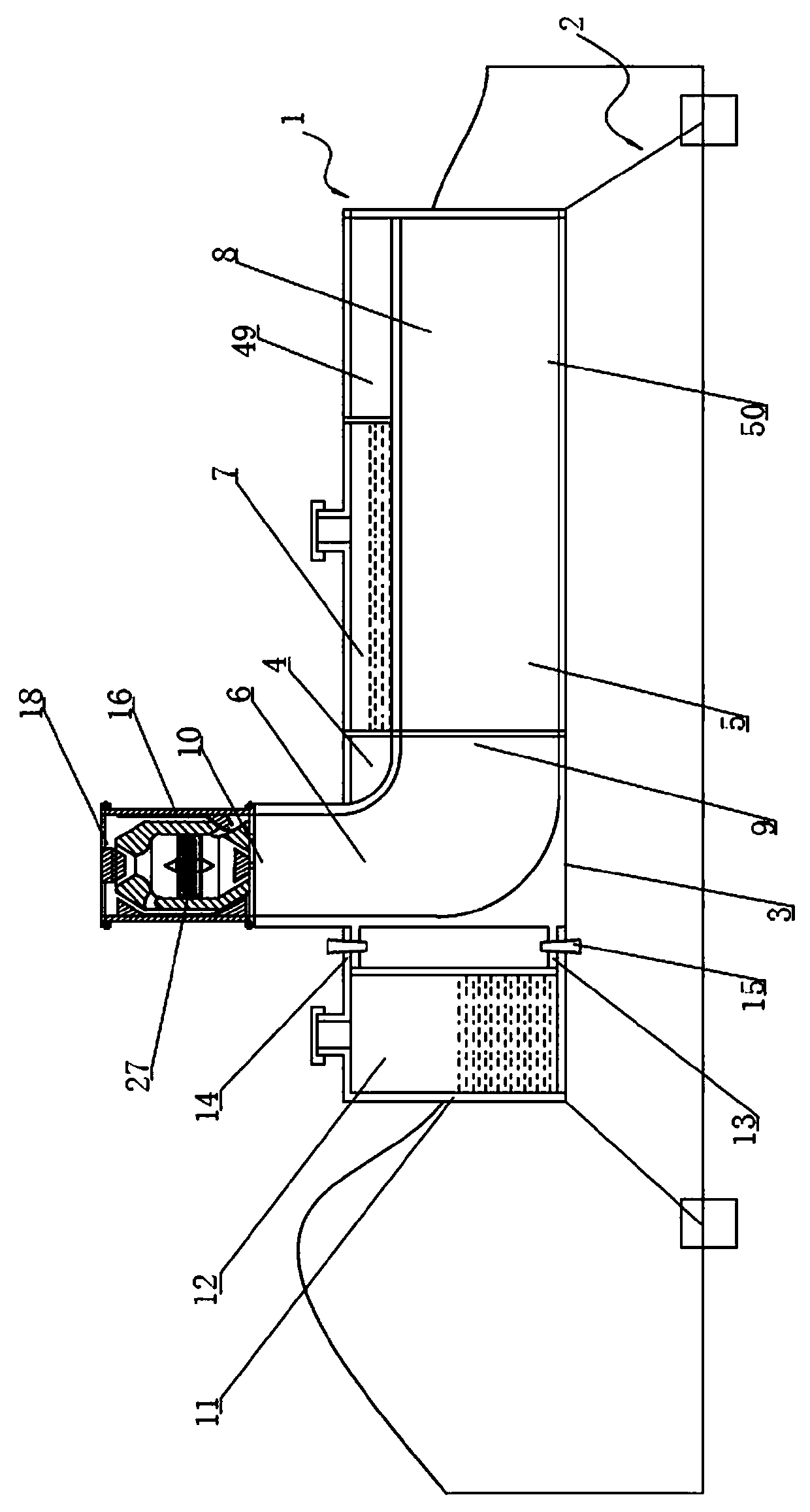
[0065] Such as figure 1 As shown, a floating breakwater with wave power generation function provided by this embodiment includes a floating body 1 and an anchoring system 2;
[0066] The floating body 1 includes:
[0067] A first box body 3, the first box body 3 includes a front cavity 4 and a rear cavity 5, both of which are arranged front and rear in a direction parallel to the sea level; the front cavity 4 forms an arc-shaped flow channel 6 The rear chamber 5 includes an upper chamber 49 and a lower chamber 50, both of which are arranged up and down in the direction perpendicular to the sea level, and the upper chamber 49 forms a first water storage bin 7; the lower chamber 50 forms A straight channel 8; the center line of the first opening 9 of the arc channel 6 is parallel to the sea level, and abuts with the opening on one side of the lower chamber 50, and its second opening 10 is higher than the sea level in the direction perpendicular to the sea level The first openi...
Embodiment 2
[0089] The general structure of the floating breakwater provided in this embodiment is consistent with that of Embodiment 1, as shown in Figure 7 shown, but the floating body 1 in this embodiment also includes an automatic collection system for floating objects on the sea;
[0090] The automatic collection system for floating objects at sea includes:
[0091] A conveyor belt assembly 35, which is located outside the opening on the side of the lower cavity 50 away from the first opening 9, and completely blocks the opening on this side; the conveyor belt 36 of the conveyor belt assembly 35 forms a 30-60° angle with the sea level angle, and is a grid structure; the driving roller 37 of the conveyor belt assembly 35 is hinged to the third bracket 39 extending outward from the first box body 3 through the first rotating shaft 38, and its driven roller 40 is passed through The second rotating shaft 41 is hinged to the first box body 3, and the driven roller 40 is higher than the ...
Embodiment 3
[0097] The general structure of the floating breakwater provided by this embodiment and the function of wave energy generation is consistent with that of Embodiment 2, as Figure 8 As shown, but in the present embodiment, a first partition 45 is provided in the lower cavity 50 of the first box body 3, and the first partition 45 extends in a direction parallel to the sea level; A second partition 46 is arranged in the first water storage bin 7, and the second partition 46 extends in a direction perpendicular to the sea level; plate 47, said third partition 47 extends in a direction perpendicular to the sea level.
[0098] All the partitions mentioned above can act as wave breakers, weaken the direct impact force of the wave current on the floating body 1, and protect the floating body 1.
PUM
 Abstract
Description
Claims
Application Information