A multi-probe star sensor on-orbit autonomous fault diagnosis and repair method
A technology of star sensor and fault diagnosis, applied in the field of satellite attitude control, can solve the problems of disturbance between data, wrong operation results, faults of imaging detectors, etc., and achieve the effect of improving product accuracy, fault tolerance and reliability.
- Summary
- Abstract
- Description
- Claims
- Application Information
AI Technical Summary
Problems solved by technology
Method used
Image
Examples
Embodiment 1
[0059] Example 1 (the power supply status of the product probe is abnormal during power-on)
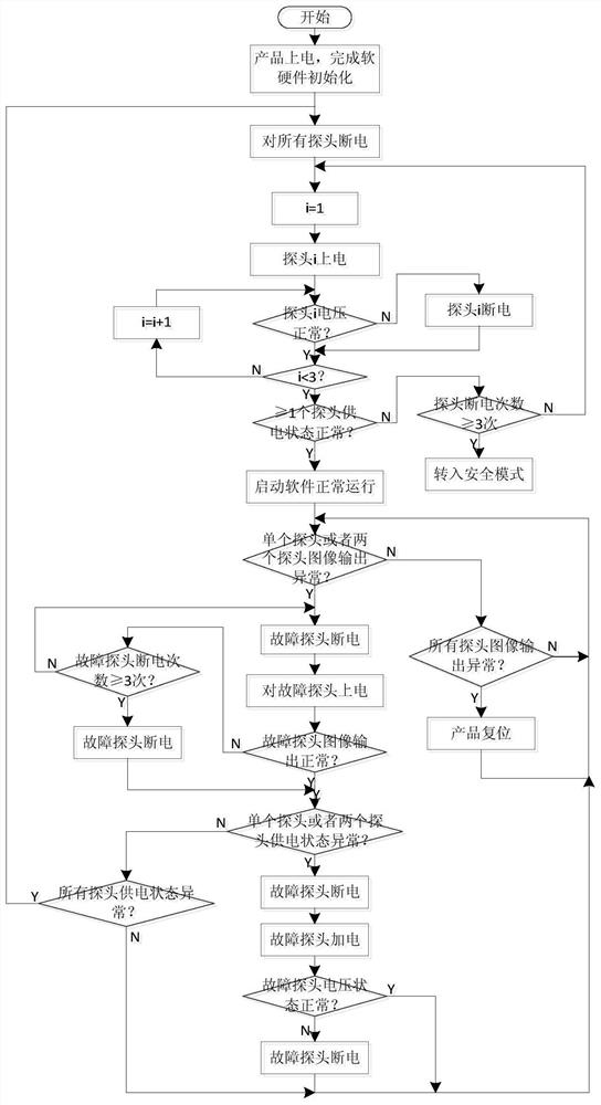
[0060] A multi-probe star sensor on-orbit autonomous fault diagnosis and repair method, the method is used for diagnosing the output image state of the probe and the power supply short circuit state of the probe, the steps of diagnosing the power supply state of the probe in the method include:
[0061] (1) The product is powered on and the hardware and software initialization is completed;
[0062] (2) Power off all probes of the product;
[0063] (3) Power on the probe 1, if the voltage status of the probe 1 is normal, then the working status of the probe 1 is normal, that is, the power supply is not interrupted, and the next step is performed;
[0064] (4) Power on the probe 2, if the voltage status of the probe 2 is normal, then the working status of the probe 2 is normal, that is, the power supply is not interrupted, and the next step is performed;
[0065] (5) Power on the pro...
Embodiment 2
[0067] Example 2 (the power supply status of the probe is abnormal during the working process of the product)
[0068] A multi-probe star sensor on-orbit autonomous fault diagnosis and repair method, the method is used for diagnosing the output image state of the probe and the power supply short circuit state of the probe, the steps of diagnosing the power supply state of the probe in the method include:
[0069] (1) Diagnose the working status of all probes. If the power supply voltage of all probes is found to be abnormal, set the working status of the product as abnormal, and proceed to the next step;
[0070] (2) Power off all probes;
[0071] (3) Power on the probe 1 again, the voltage status of the probe 1 is normal, and the working status of the probe 1 is normal, that is, the power supply is not interrupted, and the next step is performed;
[0072] (4) Power on the probe 2 again, if the voltage state of the probe 2 is abnormal, then set the working state of the probe ...
Embodiment 3
[0075] Example 3 (the output image state of a single probe is abnormal during the working process of the product)
[0076] (1) During the normal operation of the product, the output image status of all probes is monitored every cycle, and it is diagnosed that the probe 2 fails to output image data for 5 consecutive seconds, and the next step is performed;
[0077] (2) Power off the probe 2;
[0078] (3) After waiting for 2 seconds, power on the probe 2 again, and complete the reconfiguration of the probe's detector and ASIC / FPGA related registers;
[0079] (4) Re-initialize the FPGA / ASIC corresponding to probe 2;
[0080] (5) Diagnose the output image status of probe 2 again. If probe 2 still cannot output image data, repeat steps (1) to (5). After repeating 3 times, probe 2 still cannot output image data, and then set probe 2 to work. After the status is abnormal, power off the probe 2.
PUM
 Abstract
Description
Claims
Application Information
 - R&D
- Intellectual Property
- Life Sciences
- Materials
- Tech Scout
- Unparalleled Data Quality
- Higher Quality Content
- 60% Fewer Hallucinations
Browse by: Latest US Patents, China's latest patents, Technical Efficacy Thesaurus, Application Domain, Technology Topic, Popular Technical Reports.
© 2025 PatSnap. All rights reserved.Legal|Privacy policy|Modern Slavery Act Transparency Statement|Sitemap|About US| Contact US: help@patsnap.com

