
Cytomechanics characteristic measurement equipment and measurement method

A technology of mechanical properties and measuring equipment, which is applied in the field of cell-molecular signal interaction, can solve problems such as small dynamic range of measurement, limited measurement range, and inability to calculate cell Young's modulus results, etc.

Active Publication Date: 2019-12-13
SOUTH CHINA UNIV OF TECH
View PDF7 Cites 9 Cited by
  • Summary
  • Abstract
  • Description
  • Claims
  • Application Information

AI Technical Summary

Problems solved by technology

However, there are still disadvantages in this technique, namely, the small dynamic range of the measurement and the inability to measure the Young's modulus of cells
When measuring, it is necessary to use a micropipette to absorb cells or beads, and then perform a motion cycle of approach-contact-pull back. The force measurement range determined in this process cannot be too large, which limits the force measurement dynamics of this technology. range size (10 1 -10 3 pN)
In addition, the "probes" used in this technology are adsorbed cells or pellets, and a suitable cell model cannot be established, so it is also impossible to calculate a suitable cell Young's modulus result based on the force-distance curve
[0006] In addition, at present, whether it is commercial atomic force microscope or biofilm force probe technology, when measuring samples, only a specific size of petri dish can be selected, which is due to its compact structure design, which is largely limited the size of experimental samples

Method used


Image

  • Cytomechanics characteristic measurement equipment and measurement method
  • Cytomechanics characteristic measurement equipment and measurement method
  • Cytomechanics characteristic measurement equipment and measurement method

Examples


Embodiment

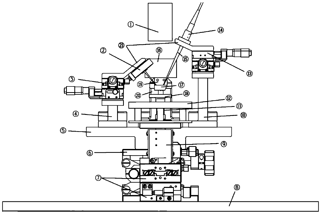
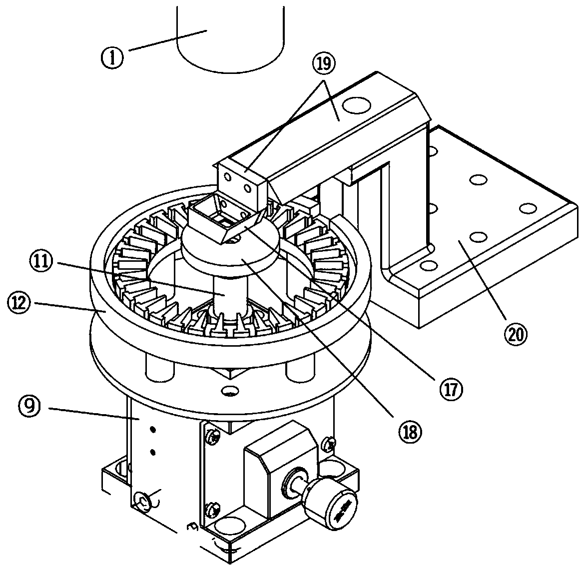
[0076] Such as figure 1 Shown is a schematic structural diagram of a cell mechanical property measurement device, including a laser force measurement system, a microscopic observation system, a position control system, a signal receiving / converting and digital control system, a post-processing software system, and a liftable stage 18;

[0077] The laser force measuring system includes a double-probe component 17, a double-probe component load-bearing indenter 16, a laser light source 14 and a position detector 2;

[0078] The microscopic observation system includes a monocular microscope 1 and a multi-light source component 12;

[0079] The position control system includes a position detector displacement controller 3, a laser light source displacement controller 13, a laser force measuring system displacement controller 6, a sample stage XY axis displacement controller 7, a sample stage Z axis displacement controller 9 and a nano Z Shaft displacement controller 11;

[0080]...


PUM


Abstract

The invention discloses cytomechanics characteristic measurement equipment. The measurement equipment comprises a laser force-measuring system, a microscopic observation system, a location control system, a signal receiving / converting and digital control system, a postprocessing software system and a liftable objective table; the laser force-measuring system comprises a dual-probe component, a dual-probe component weighted pressure head, a laser source and a location detector; the microscopic observation system comprises a monocular microscope and a multi-light source component; the location control system comprises a location detector displacement controller, a laser source displacement controller, a laser force-measuring system displacement controller, a sample table XY-axle displacementcontroller, a sample table X-axle displacement controller and a nanometer Z-axle displacement controller; the signal receiving / converting and digital control system comprises a displacement table controller, a location detector signal processing unit and a computer; and the postprocessing software system comprises a sensitivity determination module, a thermal curve analysis module, a force curveanalysis module and a global image processing module.

Description

technical field [0001] The invention relates to the field of cell molecular signal interaction in biophysics, in particular to a measuring device and a measuring method for cell mechanical properties. Background technique [0002] Cell mechanical properties are mainly cell Young's modulus and cell surface adhesion properties. In cell mechanics, the Young's modulus of the cell reflects the stiffness of the cell. The stiffness of cells is related to many physiological and pathological states. Cell surface adhesion properties refer to the mechanical properties of the interaction between cell surface molecular receptors and extracellular ligands. Physiological and pathological states of organisms or changes in the microenvironment of cells may affect the adhesion characteristics of cell surfaces. In the physiological environment, there are usually multiple receptors on the cell surface, some receptors are independent of each other, some receptors interact with each other, and...

Claims


Application Information

Patent Timeline
IPC IPC(8): G01N15/10
CPCG01N15/10G01N2015/1006G01N15/01
Inventor 辛学刚李泽诚
Owner SOUTH CHINA UNIV OF TECH
Learn More