
Sintering machine waste gas cyclic utilization system

A waste gas recycling and sintering machine technology, applied in waste heat treatment, furnaces, lighting and heating equipment, etc., can solve the problems of high operating costs and huge one-time fixed investment costs, and achieve the effect of protecting the environment and reducing total emissions

Pending Publication Date: 2019-12-17
MAANSHAN IRON & STEEL CO LTD
View PDF0 Cites 0 Cited by
  • Summary
  • Abstract
  • Description
  • Claims
  • Application Information

AI Technical Summary

Problems solved by technology

[0007] However, the above two technical paths not only have huge one-time fixed investment costs (at least more than 200 million yuan), but also high operating costs (the cost will increase by at least 20 yuan per ton of ore), and there are some harmful by-products that are inconvenient to handle Waste (low concentration sulfuric acid, catalyst)
In addition, the above two waste gas pollution control process routes have little effect on the pollution of CO and dioxin in the sintering waste gas.

Method used


Image

  • Sintering machine waste gas cyclic utilization system
  • Sintering machine waste gas cyclic utilization system
  • Sintering machine waste gas cyclic utilization system

Examples


Embodiment 1

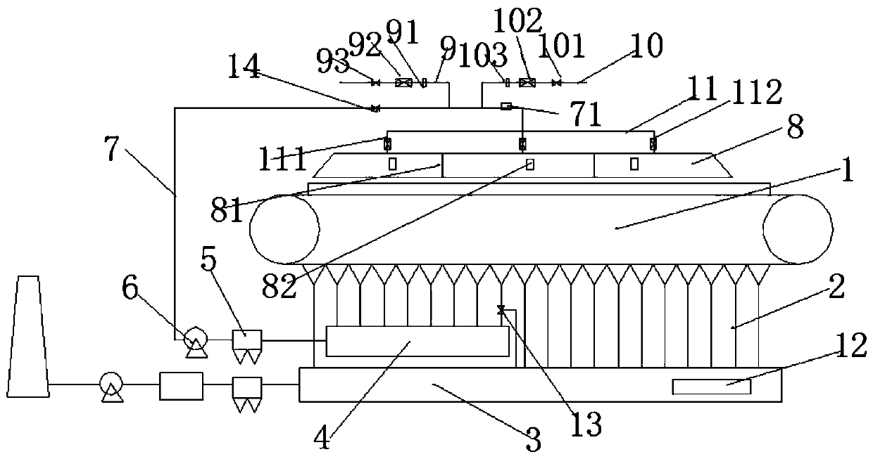
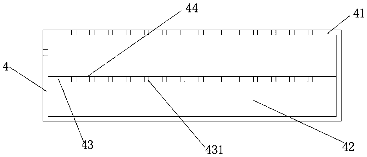
[0058] Example 1: The recycling system is connected to several exhaust branch pipes 2 at the lower part of the sintering machine 1 through the flue gas pipe 4, and the first exhaust branch pipe corresponding to the ignition section is still connected to the main exhaust pipe; the waste gas in the recycling system is fed by the circulation fan 6 After being pretreated by the dust collector, the circulating exhaust gas is sent to the flue gas hood 8 above the sintering machine 1 for distribution and recycling.

[0059] A cut-off valve 14 is arranged on the recovery pipeline 7, and an oxygen supply mechanism 9 is arranged behind the valve. The oxygen supply pipeline is connected with the recovery pipeline 7, and the online oxygen detection instrument 71 of the recovery pipeline 7 and the regulating valve and flow meter on the oxygen supply pipeline are passed through. The closure can adjust and supplement the oxygen content of the exhaust gas in the fume hood to meet the productio...


PUM


Abstract

The invention relates to the field of sintering machine waste gas treatment equipment, in particular to a sintering machine waste gas cyclic utilization system. The waste gas cyclic utilization systemcomprises a recycling pipeline, the recycling pipeline is connected with a plurality of air suction branch pipes in an air suction branch pipe set, and the other end is connected with a smoke cover.The smoke cover is located above a sintering machine. The recycling pipeline is further connected with an oxygen supply mechanism for oxygen supplementing. The oxygen supply mechanism comprises an oxygen supply pipeline connected with an oxygen supply component. The sintering machine waste gas cyclic utilization system is disclosed. Through optimization of the air inflow of the cyclic utilizationsystem and oxygen re-supply, sintering main extracted waste gas can be cyclically utilized to the maximum, and multi-pollutant technology emission reduction is achieved in combination with the sintering technology characteristics.

Description

technical field [0001] The invention relates to the field of sintering machine waste gas treatment equipment, in particular to a sintering machine waste gas recycling system. Background technique [0002] The sintering process in the iron and steel industry is suitable for processing bulk iron powder ore, with low cost and strong practicability, and is currently the main raw material supply method for blast furnace smelting. However, there are also problems such as high energy consumption and large exhaust pollution. [0003] Today, the national standards for pollutant emissions in the iron and steel industry continue to increase. In 2020, the main exhaust gas emissions from the sintering industry are required to meet the ultra-clean emission requirements (under the condition of an oxygen content of 16%, the particulate matter is less than 10mg / m, and the SO2 is less than 35mg. / m, NOx less than 50mg / m). [0004] At present, almost all sintering systems cannot achieve it, ...

Claims


Application Information

Patent Timeline
IPC IPC(8): F27D17/00
CPCF27D17/008F27D17/004
Inventor 周江虹刘益勇张晓萍于敬吴志勇杨业王军曹建民王文节永烈艾文兵
Owner MAANSHAN IRON & STEEL CO LTD
Learn More