Sintering flue gas desulfurization and denitrification apparatus
A technology for desulfurization, denitrification, and sintering flue gas, which is applied in the separation of dispersed particles, chemical instruments and methods, separation methods, etc., and can solve the problem of insufficient contact between absorbing liquid and flue gas, poor flue gas treatment effect, and high consumption of absorbing liquid. To improve the contact probability and contact time, improve the desulfurization effect, and improve the absorption effect
- Summary
- Abstract
- Description
- Claims
- Application Information
AI Technical Summary
Problems solved by technology
Method used
Image

Examples
Embodiment 1
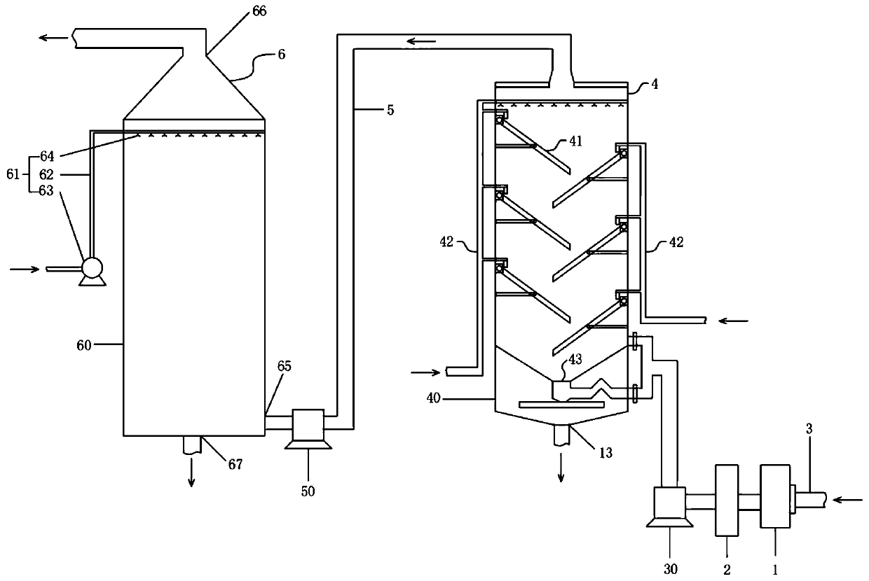
[0046] Such as figure 1 As shown, a sintering flue gas desulfurization and denitrification device 6 in this embodiment includes an oxidation device 1, a dust removal device 2, a gas distribution main pipe 430, a desulfurization device 4, a gas transmission pipeline 5 and a denitrification device 6 arranged in sequence along the airflow direction;
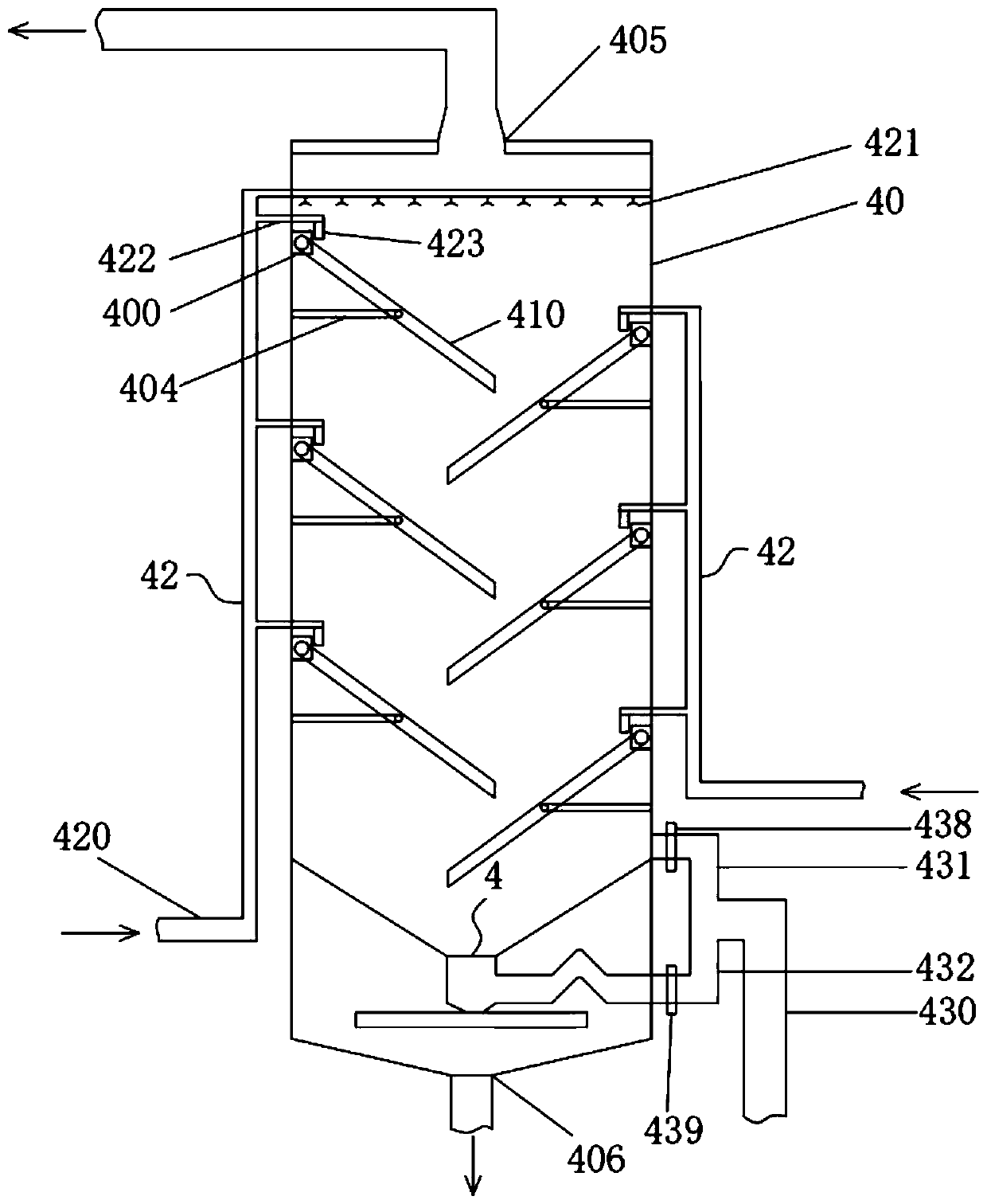
[0047] The desulfurization device 4 includes a desulfurization tower body 40, a slant plate filter assembly 41 arranged inside the desulfurization tower body 40, a desulfurization spray assembly 42 for supplying absorption liquid into the desulfurization tower body 40, and a gas distribution main pipe 430 for entering The flue gas is delivered to the gas distribution component 43 in the desulfurization tower body 40;
[0048]The sloping plate filter assembly 41 includes a number of sloping filter plates 410 arranged staggeredly on the inner wall of the desulfurization tower body 40 , one end of the sloping filter plates 410 is conne...
Embodiment 2
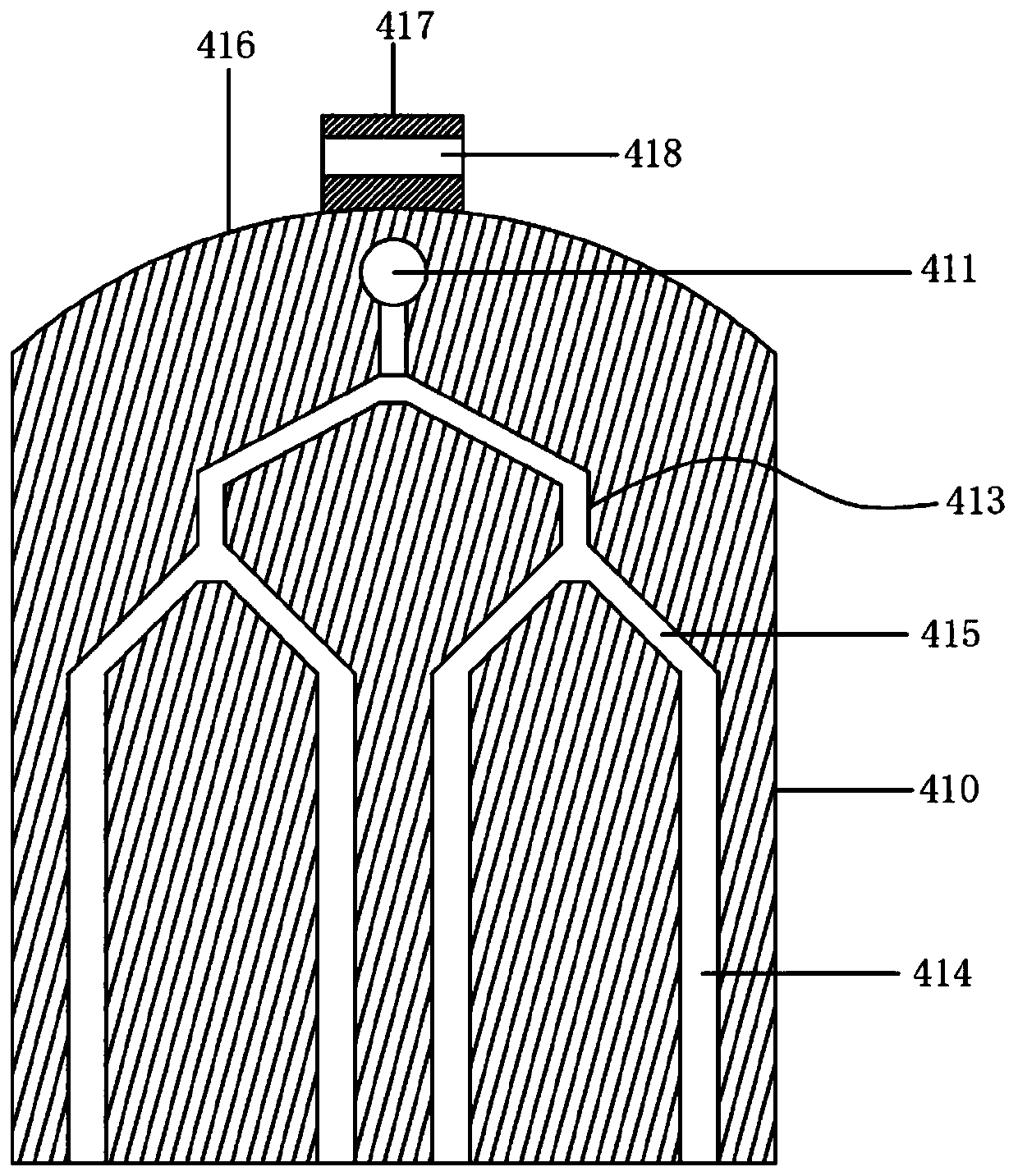
[0058] This embodiment is a further improvement on the basis of Embodiment 1, refer to Figure 2-5 , in this embodiment, one end of the sloping filter plate 410 connected to the inner wall of the desulfurization tower body 40 has an arc-shaped end edge 416, a connecting block 417 is fixedly connected to the arc-shaped end edge 416, and a connecting hole 418 is opened on the connecting block 417 . An installation block 400 is fixedly connected to the inner wall of the desulfurization tower body 40, and the installation block 400 is provided with an installation groove 401 for the connection block 417 to be inserted into. The pin shaft 403 passing through the connection hole 418; the inner wall of the desulfurization tower body 40 is also fixedly connected with a telescopic strut 404, and the other end of the telescopic strut 404 is rotatably connected with the middle part of the filter swash plate 410, and the telescopic strut 404 is selected from existing The conventional tel...
Embodiment 3
[0065] This embodiment is a further improvement on the basis of embodiment 2, refer to Figure 6-7 , in this embodiment, the air distribution assembly 43 includes a first air distribution pipe 431 and a second air distribution pipe 432 that communicate with the air intake pipe 3 through the air distribution main pipe 430. The air distribution main pipe 430 communicates with the second air distribution pipe 432. The adapter pipe head 433 communicated with the outlet end of the adapter pipe head 433, the cone air distribution cylinder 434 communicated with the upper end of the adapter pipe head 433, and the liquid guide box 435 communicated with the lower end of the adapter pipe head 433; the bottom of the liquid guide box 435 is provided with a plurality of liquid outlets hole, the lower end of the adapter pipe head 433 communicates with the inside of the liquid guiding box 435 through a constricted tube 436 . The second air distribution pipe 432 is provided with a liquid block...
PUM
 Abstract
Description
Claims
Application Information
 - R&D
- Intellectual Property
- Life Sciences
- Materials
- Tech Scout
- Unparalleled Data Quality
- Higher Quality Content
- 60% Fewer Hallucinations
Browse by: Latest US Patents, China's latest patents, Technical Efficacy Thesaurus, Application Domain, Technology Topic, Popular Technical Reports.
© 2025 PatSnap. All rights reserved.Legal|Privacy policy|Modern Slavery Act Transparency Statement|Sitemap|About US| Contact US: help@patsnap.com