
Welding method of high-melting-point foam metal plates and metal plates

A welding method and metal plate technology, applied in welding equipment, metal processing equipment, sheet/plate, etc., can solve the problems of low mechanical properties of joints, easy to burn through, etc. Corrosion performance improvement effect

Active Publication Date: 2019-12-20
北京碳垣智能科技发展有限公司
View PDF6 Cites 3 Cited by
  • Summary
  • Abstract
  • Description
  • Claims
  • Application Information

AI Technical Summary

Problems solved by technology

[0004] The purpose of the embodiment of the present invention is to provide a welding method and metal plate of high-melting point foamed metal plate, which overcomes the problems of easy burn-through and low mechanical properties of joints during the welding process of high-melting point foamed metal plate, and improves the welding quality of the finished product at the same time. Electrochemical corrosion resistance, simplifies the welding process

Method used


Image

  • Welding method of high-melting-point foam metal plates and metal plates
  • Welding method of high-melting-point foam metal plates and metal plates
  • Welding method of high-melting-point foam metal plates and metal plates

Examples


Embodiment 1

[0038] This embodiment relates to a welding method for a high-melting-point foamed metal plate. The foamed metal plate is a foamed nickel plate. There are continuous and through holes in the foamed nickel plate. The thickness is 5mm and the porosity is 95%. The specific welding method Include the following steps:

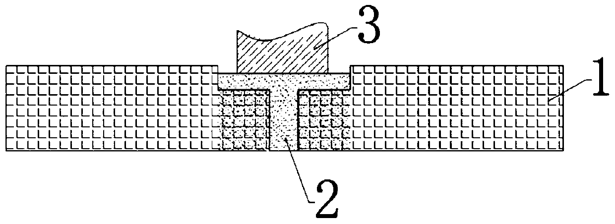
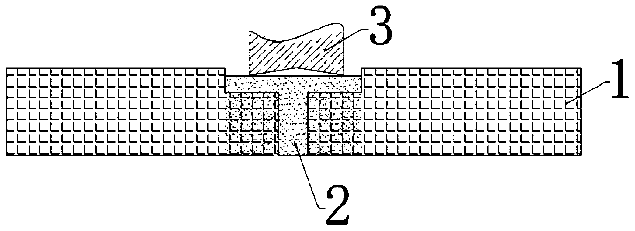
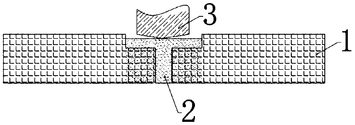
[0039] Place the two foam metal plates 1 to be welded butt-jointly and fix them on the fixture base, and reserve a 1mm butt-joint gap;

[0040] 400 mesh, 95% copper powder welding auxiliary material is filled in the hole at the butt end of the foam metal plate and in the butt joint gap, and the powdery welding auxiliary material overflows the surface of the butt end of the foam metal plate; specifically, the Copper powder welding auxiliary material is sprayed on the surface of the butt end of the foam metal plate. Since the foam metal plate has continuous and through holes, the copper powder welding auxiliary material will penetrate into the interior of the foam met...

Embodiment 2

[0046] This embodiment relates to a welding method for a high-melting point foamed metal plate. The foamed metal plate is a foamed titanium plate. There are continuous and through holes in the foamed titanium plate. The thickness is 4mm and the porosity is 98%. The specific welding method Include the following steps:

[0047] Place the two foam metal plates to be welded butt, clamp and fix them on the fixture base, and reserve a 0.5mm butt gap;

[0048] Fill the 300-mesh titanium powder welding auxiliary material in the hole at the butt end of the foam metal plate and in the butt gap, and the powdery welding auxiliary material overflows the surface of the butt end of the foam metal plate; specifically, the titanium powder welding auxiliary material can be sprayed On the surface of the butt end of the foam metal plate, since the foam metal plate has continuous and through holes, the titanium powder welding auxiliary material will penetrate into the interior of the foam metal pl...


PUM

PropertyMeasurementUnit
Graininessaaaaaaaaaa

Abstract

The invention relates to the technical field of welding, and particularly discloses a welding method of high-melting-point foam metal plates. The foam metal plates are internally provided with continuous through holes, and the method comprises the following steps of clamping and fixing two to-be-welded foam metal plates after butt joint, and reserving a butt joint gap; filling the holes of the butt joint ends of the foam metal plates and the butt joint gap with a powdery welding auxiliary material, wherein the powdery welding auxiliary material overflows from the surfaces of the butt joint ends of the foam metal plates; grinding the powdered welding auxiliary material along the butt joint gap; performing stirring and friction welding along the butt joint gap. According to the embodiment, the problems of easy burnthrough, low joint mechanical property and the like in the welding process of the high-melting-point foam metal plates are solved, the electrochemical corrosion resistance of awelded finished product is improved, and the welding process is simplified.

Description

technical field [0001] The embodiments of the present invention relate to the field of welding technology, in particular to a welding method and metal plate of high melting point foamed metal plates. Background technique [0002] Metal foam is a new type of functional material. Due to its special three-dimensional structure, it has many excellent properties different from traditional materials, including cushioning and shock absorption, electromagnetic shielding, sound insulation and noise reduction, heat insulation, etc., especially Its porosity can reach more than 98%, almost fully transparent structure, small pressure drop, large flow rate, excellent permeability, and is an ideal filter material. The fine pores in the metal foam can trap and block solid impurities in the fluid phase, remove impurity solid particles in the fluid phase, and then achieve separation and purification. With the development of metal foam, especially in the field of separation and filtration, th...

Claims


Application Information

Patent Timeline
IPC IPC(8): B23K20/12B23K20/16F16S1/00
CPCB23K20/129B23K20/16F16S1/00
Inventor 王卫兵侯红亮赵大龙段学平牛涛赵志勇
Owner 北京碳垣智能科技发展有限公司
Learn More