
Remote monitoring system

A remote monitoring and perception layer technology, applied in the transmission system, general control system, control/regulation system, etc., can solve problems such as increased power consumption, untimely alarm, life-threatening threats, etc., to ensure reliability and stability , improve accuracy and reliability, and reduce system power consumption

Inactive Publication Date: 2019-12-20
NANJING UNIV OF AERONAUTICS & ASTRONAUTICS
View PDF7 Cites 6 Cited by
  • Summary
  • Abstract
  • Description
  • Claims
  • Application Information

AI Technical Summary

Problems solved by technology

[0002] The traditional river water quality monitoring collection terminal is installed in a fixed position in the river water. Although the river water is diffuse, for some places with complex water environment, deep water area and slow water flow, once the water environment is polluted, due to Different diffusion rates will lead to different degrees of pollution in the upper, middle and lower layers of the river, resulting in inaccurate detection, untimely alarm, and incomplete assessment; at the same time, in the later stage of pollutant diffusion, pollutants are likely to gradually deposit and become rich. Collected to the bottom of the water, if the water quality monitoring collection terminal is installed in the middle and upper layers of the river, once the pollutants are deposited in the lower layer of the water, the alarm will be released due to the detection of no pollution, which will seriously damage the ecological environment and threaten people's lives.
[0003] River water quality collection terminals are generally installed at the corners, intersections, and sewage outlets of rivers. For the same river, there are generally multiple monitoring sections. The traditional method is to simultaneously collect water quality status data from multiple sections, that is, each collection terminal It is in working condition for a long time, which often increases the loss of power consumption and shortens the hardware life of each section
For the sensor of the acquisition terminal, long-term work will lead to failure. For the fault detection of the sensor, the traditional solution is to diagnose the fault when the sensor does not return data. If the fault is only detected in this way, the fault will often be missed. The reported situation is that the sensor is faulty but the data exceeds the value but the fault is not detected

Method used


Image

  • Remote monitoring system

Examples


Embodiment Construction

[0019] In order to make the technical means, creative features, goals and effects achieved by the present invention easy to understand, the present invention will be further described below in conjunction with specific illustrations.

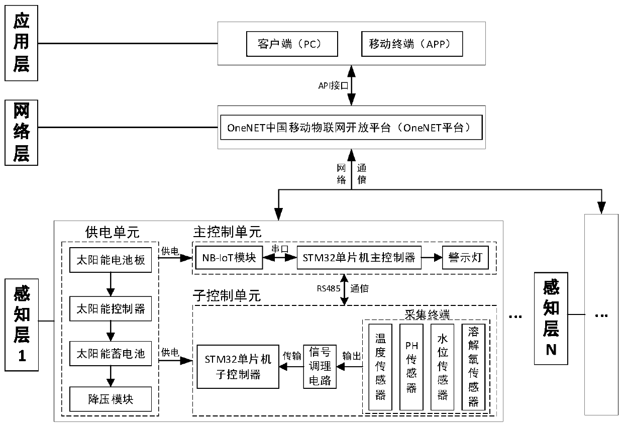
[0020] Such as figure 1 As shown, a remote monitoring system includes a perception layer, a network layer and an application layer, and the perception layer includes a power supply unit, a main control unit and a sub-control unit, and the perception layer works in PSW power saving mode and DRX discontinuous reception mode , can greatly reduce the power consumption of the sensing layer hardware and prolong its service life, wherein the power supply unit includes a solar panel, a solar controller, a solar battery and a step-down module to provide power for the main control unit and the sub-control unit; The main control unit includes a STM32 single-chip main controller, NB-IoT module and warning lights. The main control unit is installed by the ri...


PUM


Abstract

The invention discloses a remote monitoring system. The remote monitoring system comprises a sensing layer, a network layer, and an application layer, wherein the sensing layer comprises a power supply unit, a main control unit, and a sub-control unit; the power supply unit is used for providing a power source; the main control unit is arranged by a river and mainly comprises a master controller and an NB-IoT module; the sub-control unit is arranged on a ball screw capable of moving up and down, and mainly comprises a sub-controller; the network layer comprises an internet-of-things platform;the application layer comprises a client and a mobile terminal; the sensing layer and the network layer are in network connection based on the LwM2M protocol; and the network layer and the applicationlayer exchange data through an API (Application Program Interface). Due to the adoption of the scheme, a manager can realize functions such as remote monitoring (of river water quality and the like),sensor fault alarm and remote setting of monitoring parameters through a PC (Personal Computer) and a mobile phone; and the system has the advantages of low power consumption, low cost, stability andreliability.

Description

technical field [0001] The invention relates to the field of ecological environment protection, in particular to a remote monitoring system. Background technique [0002] The traditional river water quality monitoring collection terminal is installed in a fixed position in the river water. Although the river water is diffuse, for some places with complex water environment, deep water area and slow water flow, once the water environment is polluted, due to Different diffusion rates will lead to different degrees of pollution in the upper, middle and lower layers of the river, resulting in inaccurate detection, untimely alarm, and incomplete assessment; at the same time, in the later stage of pollutant diffusion, pollutants are likely to gradually deposit and become rich. Collected to the bottom of the water, if the water quality monitoring collection terminal is installed in the middle and upper layers of the river, once the pollutants are deposited in the lower layer of the ...

Claims


Application Information

Patent Timeline
Patent Type & Authority Applications(China)
IPC IPC(8): G05B19/418G08B19/00H04L29/08H04W4/38
CPCG05B19/4183G05B19/4185G08B19/00H04L67/025H04L67/125H04W4/38Y02P90/02Y02D30/70
Inventor 李成刚吴泽枫宋勇陈飞翔储亚东
Owner NANJING UNIV OF AERONAUTICS & ASTRONAUTICS
Learn More