Treatment device and process integrating VOCs purification and denitration

A treatment device and treatment process technology, applied in chemical instruments and methods, incinerators, lighting and heating equipment, etc., can solve problems such as increased operating energy consumption, non-compliance with process requirements, etc. Efficient removal effect

Pending Publication Date: 2019-12-24
SHANGHAI LANKE PETROCHEM ENG & TECH
View PDF2 Cites 6 Cited by
  • Summary
  • Abstract
  • Description
  • Claims
  • Application Information

AI Technical Summary

Problems solved by technology

Since the SCR reaction needs to be carried out at a certain temperature (200-400°C), and the temperature of the exhaust gas at the outlet of the RTO device is not higher than 100°C after heat recovery, additional heat is required to reheat the exhaust gas bef

Method used


Image

  • Treatment device and process integrating VOCs purification and denitration
  • Treatment device and process integrating VOCs purification and denitration
  • Treatment device and process integrating VOCs purification and denitration

Examples


Embodiment 1

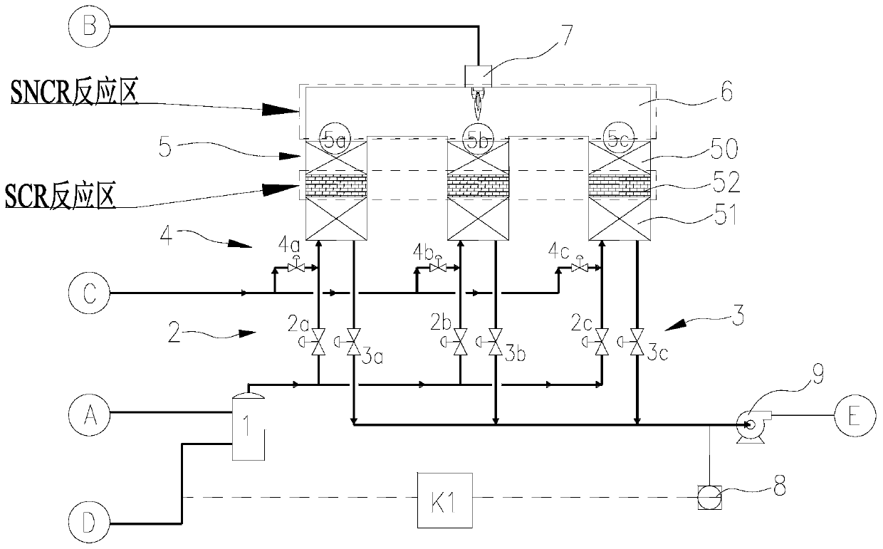
[0065] Such as figure 1 As shown, it is a treatment device integrating VOCs purification and denitrification, including an RTO reactor, which includes a combustor 6 and several regenerators 5 connected to each other, and the combustor 6 is located in the regenerator 5 the upper part; any regenerator 5 includes an upper regenerator 50, a lower regenerator 51 and an SCR catalyst bed 52 in the middle; Valve 3, a purge valve 4; the input end of the inlet valve is connected to the buffer tank 1, and the buffer tank 1 is connected to the VOCs waste gas A pipeline and the ammonia gas D pipeline; the input end of the purge valve is connected to the purge tank Gas supply pipeline; the top of the combustion chamber 6 is also provided with a burner 7, and the input end of the burner 7 is connected to the fuel gas B pipeline.

[0066] In this embodiment, through the innovative device design, firstly, a buffer tank 1 is set up so that VOCs waste gas A and ammonia gas D are mixed before en...

Embodiment 2

[0073] This embodiment is a process method integrating VOCs purification and denitrification, combining figure 1 shown, including the following steps:

[0074] S1, heat release stage of heat accumulator: both VOCs waste gas A and ammonia gas D are passed into the buffer tank 1, and after being fully mixed in the tank (to make quantitative NH 3 and VOCs waste gas are uniformly mixed in the tank through the distributor before entering the RTO reactor), and enter any regenerator 5 through the intake valve 2, the lower regenerator 51 and the upper regenerator 50 in the regenerator 5 The exhaust gas is heated step by step; at this time, the regenerator is in a heat release state;

[0075] S2, VOCs oxidation reaction and SNCR reaction stage: the exhaust gas enters the combustion chamber 6 after being heated by the regenerator, and the temperature in the combustion chamber 6 is controlled at 650-800°C, so that the VOCs exhaust gas A in the mixed gas is fully oxidized into CO 2 and ...


PUM


Abstract

The invention discloses a treatment device and process integrating VOCs purification and denitration. The treatment device includes an RTO reactor; the RTO reactor comprises a combustion chamber and aplurality of regenerative chambers, the combustion chamber and the regenerative chambers are communicated, and the combustion chamber is located on the upper portions of the regenerative chambers; each regenerative chamber comprises an upper-section heat accumulator, a lower-section heat accumulator and a middle SCR catalyst bed layer; an air inlet valve, an air outlet valve and a purging valve are arranged at the bottom of any regenerative chamber; the input end of the gas inlet valve is connected with a buffer tank, and the buffer tank is connected with a VOCs waste gas pipeline and an ammonia gas pipeline; the input end of the purge valve is connected with a purge gas supply pipeline; a combustor is further arranged at the top of the combustion chamber, wherein the input end of the combustor is connected with a fuel gas pipeline. According to the device, the high-temperature environment in the RTO reactor is fully utilized in the SNCR-SCR reaction, ultra-clean emission of VOCs andNOx is achieved, and the purpose of reducing energy consumption is achieved. Meanwhile, a corresponding treatment process is provided, so that VOCs can be effectively purified and NOx can be effectively removed at the same time, and the operation is reliable.

Description

technical field [0001] The invention belongs to the technical field of industrial waste gas treatment, and relates to a treatment device and process integrating VOCs purification and denitrification. Background technique [0002] Volatile Organic Compounds (Volatile Organic Compounds, hereinafter referred to as VOCs) is a general term for a series of volatile, flammable and toxic organic compounds, including alkanes, alkenes, aromatic hydrocarbons, alcohols, aldehydes, ketones, halogenated hydrocarbons, etc. VOCs is a general term for organic compounds released into the air by volatilization of high vapor pressure materials during storage and loading and unloading of oil products and chemical materials. VOCs not only cause a great waste of resources but also cause serious air pollution. [0003] For low-concentration VOCs waste gas with large air volume, low concentration, and no recovery value, the VOCs medium is usually destroyed by means of regenerative incineration (RTO)...

Claims


Application Information

Patent Timeline
IPC IPC(8): B01D53/86B01D53/56F23G7/06
CPCB01D53/56B01D53/8631F23G7/06Y02A50/20
Inventor 杜先马洪玺孙国辉
Owner SHANGHAI LANKE PETROCHEM ENG & TECH
Why Eureka
Try Eureka