
High-speed large-range continuous tunable method for DFB array

A large-scale, array technology, applied to the structure of the optical resonant cavity, etc., can solve problems such as limitations, inability to scan the frequency range without interval splicing and coverage, and severe temperature fluctuations of the target

Active Publication Date: 2019-12-27
HARBIN INST OF TECH
View PDF10 Cites 10 Cited by
  • Summary
  • Abstract
  • Description
  • Claims
  • Application Information

AI Technical Summary

Problems solved by technology

Therefore, in the DFB array, only through current tuning between adjacent single diodes, it is not possible to achieve seamless splicing and coverage of the frequency sweep range. In comparison, the DFB temperature tuning coefficient is large, but the temperature tuning can cover adjacent diodes. The wavelength can be spliced ​​without intervals, but the temperature response speed is slow, and the temperature system has a large inertia, which leads to severe oscillations at the target temperature, which is not conducive to closed-loop feedback control to achieve the stability of the tuning process or optical frequency nonlinear correction
This limits its application in specific communication occasions and optical sensing fields (such as optical frequency domain reflection fiber optic link diagnosis and sensing systems, frequency modulation continuous wave ranging systems, etc.)

Method used


Image

  • High-speed large-range continuous tunable method for DFB array
  • High-speed large-range continuous tunable method for DFB array
  • High-speed large-range continuous tunable method for DFB array

Examples


Embodiment Construction

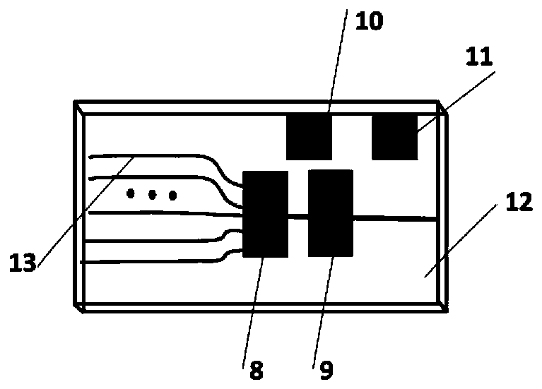
[0023] figure 1 It is a schematic diagram of the structure of a typical DFB array laser. Usually, it is composed of parallel laser diodes and a multimode interference coupler. For the D66 laser of Japan's FITEL company, it consists of 12 diodes with a wavelength spacing of 3.5nm. constitute. Temperature is typically used in its application to tune each diode to sweep across the 3.5 nm wavelength range. However, the current tuning sensitivity of this laser is very low, and only about 1nm can be tuned within its safe current range. However, in the solution proposed in this patent, temperature tuning is not used. Instead, current tuning is performed on each single tube and an attempt is made to expand the single tube frequency to achieve a single tube tuning range beyond the inherent wavelength spacing of adjacent diodes. For the D66 model For lasers, this value is 3.5nm.

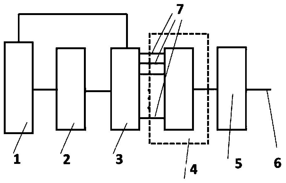
[0024] figure 2 It is the core process of the high-speed and large-range continuous tunable method of ...


PUM


Abstract

The invention provides a method for realizing high-speed large-range continuous tunability through cooperative work of single-tube frequency expansion and multi-tube time-sharing switching in a DFB array laser device. Optical frequency range expansion is carried out on swept-frequency light outputted through current tuning in a single tube, large wavelength tuning is achieved through small-range current tuning, and the tuning range is made to be not smaller than an inherent wavelength interval between adjacent diodes in the DFB array laser device. Different laser diodes in the DFB array are sequentially switched through a control module, so high-speed large-range continuous tunability in the DFB array is realized. Preferably, the cascaded four-wave mixing technology can be utilized for expanding the tuning range of the single laser diode in the DFB array. Compared with a method for realizing wavelength tuning and waveband coverage through temperature tuning of each laser diode in a traditional DFB array, the method is advantaged in that wavelength tuning can be realized completely by virtue of current without temperature, so high-speed large-range continuous tuning can be realized,and the DFB array can be quickly locked on a certain wavelength and a certain channel. The current tuning is beneficial to closed-loop control of external tuning, for example, the output optical frequency of the laser device can be linearized by using control means such as pre-correction or an optical phase-locked loop and the like.

Description

technical field [0001] The invention belongs to the field of semiconductor lasers, in particular to a method for realizing high-speed and large-range continuous tuning in a DFB array laser. Background technique [0002] Distributed feedback laser DFB array laser is a very important light source in the field of optical communication. It is widely used in optical transmission network and optical interconnection and other WDM large-capacity communication systems. The DFB array can cover the entire C-band through wavelength tuning. The monolithic integrated DFB array generally consists of a plurality of diodes (PDs) with a certain interval on the wavelength, a multimode interference coupler (MMI) and a semiconductor optical amplifier (SOA) in structure. In the modulation mode, thermal tuning is usually used to realize the wavelength tuning of different diodes, so as to cover the entire communication C-band. The tuning coefficient of DFB current tuning is small, so for a single ...

Claims


Application Information

Patent Timeline
Patent Type & Authority Applications(China)
IPC IPC(8): H01S5/12
CPCH01S5/12
Inventor 崔继文赵士元
Owner HARBIN INST OF TECH
Learn More