A sorting device for centralized treatment of dry powder tanks, demolition and discharge liquid

A centralized processing and sorting device technology, which is applied to the surface coating liquid device, special surface, solid waste removal, etc., can solve the problems of long drainage process, affecting work efficiency, wasting time, etc., and achieve faster pouring speed , Improve work efficiency and reduce residues

Active Publication Date: 2020-07-10
THE FIRST PEOPLES HOSPITAL OF CHANGZHOU
View PDF10 Cites 0 Cited by
  • Summary
  • Abstract
  • Description
  • Claims
  • Application Information

AI Technical Summary

Problems solved by technology

[0002] When the dry powder tank is in use, there is only dry powder inside. After use, there will be machine-filled water inside the dry powder tank, and the dry powder will remain inside the dry powder tank. After use, the dry powder tank needs to be drained and drained. Recycling, the drainage process is long, because the powder tank only has two small holes at the upper and lower ends, which can only drain water but not powder, and the drainage speed is very slow, which is a waste of time, and often the drainage is not clean, and the inside of the dry powder tank The dry powder does not belong to the recyclable part, thus resulting in incomplete garbage classification
[0003] The existing garbage disposal device, which is used to dispose of the dry powder tanks after use, can only recycle the dry powder tanks together with the water and dry powder inside them at the same time, and cannot classify the water and dry powder inside the dry powder tanks and the dry powder tanks themselves Recycling is not convenient for subsequent unified treatment, and after the existing garbage disposal device treats the dry powder tank, a large amount of residual dry powder and water will adhere to the inside, which is difficult to clean; if manual processing is used for classification and recycling, it will not only affect Work efficiency, but also make the work intensity greater

Method used


Image

  • A sorting device for centralized treatment of dry powder tanks, demolition and discharge liquid
  • A sorting device for centralized treatment of dry powder tanks, demolition and discharge liquid
  • A sorting device for centralized treatment of dry powder tanks, demolition and discharge liquid

Examples


Embodiment 1

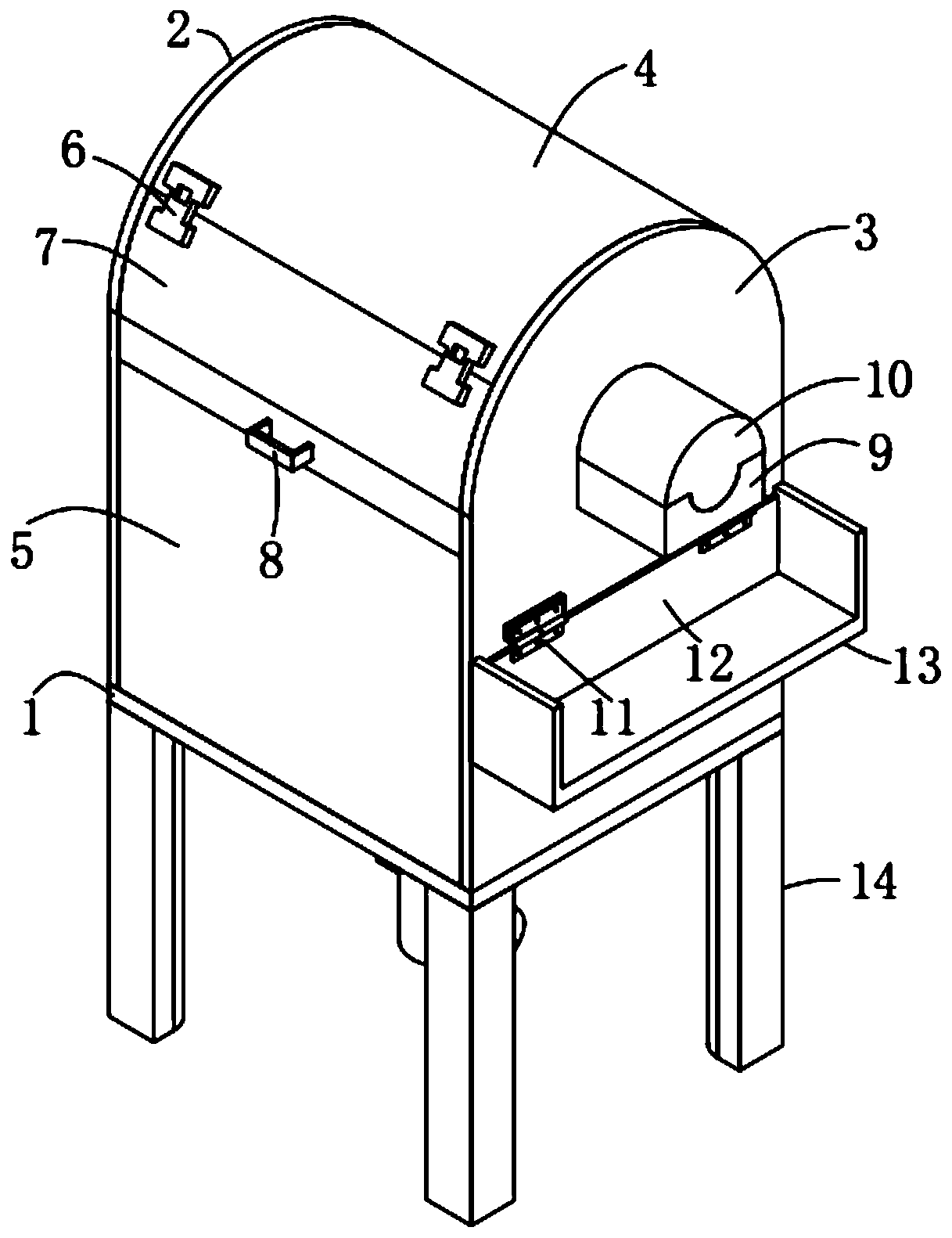
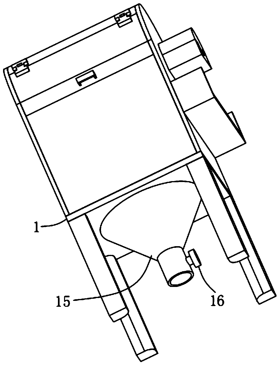
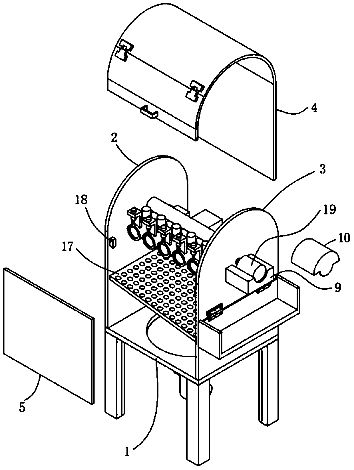
[0053] A sorting device for centralized processing of dry powder tanks, demolished and drained liquids, such as Figure 1-5 As shown, it includes a base plate 1, four legs 14, a first side plate 2, a second side plate 3, a front cover plate 5, a rear cover plate 4, a drive turning unit 37, a demolition liquid drainage unit 24, and a separation plate 17 And collecting bucket 15, described base plate 1 is a square base plate, and four described supporting legs 14 are all fixed and symmetrically installed on the bottom four corners of described base plate 1, and described first side plate 2 and described second side plate 3 fixedly installed on both sides of the upper part of the base plate 1 respectively, and the first side plate 2 and the second side plate 3 are arranged symmetrically, the front cover plate 5 is fixedly installed on the upper front part of the base plate 1, And the two sides of the front cover 5 are respectively fixedly connected with the first side plate 2 and...

Embodiment 2

[0076] The difference from Example 1 is that the inner surface of the collection bucket 15 is also provided with a protective layer, and the protective layer is prepared by the following method:

[0077] Take the following raw materials and weigh them by weight: 20 parts of epoxy resin, 12 parts of calcium carbonate powder, 13 parts of copper oxide powder, 17 parts of polytetrafluoroethylene, 8 parts of talcum powder, 10 parts of graphite, 8 parts of acrylic emulsion, alcohol ester 2 parts of twelve, 2 parts of triethanolamine, 1 part of emulsified silicone oil and 30 parts of water;

[0078] S1. Add the weighed acrylic emulsion, alcohol ester dodecane, triethanolamine, emulsified silicone oil and water into the mixer and stir for 20 minutes at a stirring speed of 600r / min to prepare a mixed solution;

[0079] S2, adding epoxy resin, calcium carbonate powder, copper oxide powder, polytetrafluoroethylene, talc powder and graphite into the pulverizer and pulverizing until the pa...

Embodiment 3

[0085] The difference with embodiment 2 is the preparation of protective layer, and its specific preparation method is as follows:

[0086] Take the following raw materials and weigh them by weight: 24 parts of epoxy resin, 13 parts of calcium carbonate powder, 13 parts of copper oxide powder, 19 parts of polytetrafluoroethylene, 9 parts of talcum powder, 11 parts of graphite, 9 parts of acrylic emulsion, alcohol ester 3 parts of twelve, 3 parts of triethanolamine, 2 parts of emulsified silicone oil and 35 parts of water;

[0087] S1. Add the weighed acrylic emulsion, alcohol ester dodecane, triethanolamine, emulsified silicone oil and water into the mixer and stir for 25 minutes at a stirring speed of 650r / min to prepare a mixed solution;

[0088] S2, adding epoxy resin, calcium carbonate powder, copper oxide powder, polytetrafluoroethylene, talc powder and graphite into the pulverizer and pulverizing until the particle diameter of the material is not greater than 100nm, so a...


PUM


Abstract

The invention discloses a sorting device realizing concentrated treatment of dismantling and draining for a dry powder can. The device comprises a bottom plate, four supporting legs, a first side plate, a second side plate, a front cover plate, a rear cover plate, a driving turnover unit, a dismantling and draining unit, a separating plate and a collecting hopper, wherein the four supporting legsare fixedly mounted at four corners of the bottom of the bottom plate in a symmetrically mode, and the first side plate and the second side plate are fixedly mounted on the two sides of the upper portion of the bottom plate correspondingly. According to the sorting device, the used dry power can can be treated without using manual operation, the working efficiency is effectively improved, and thethe working intensity is effectively reduced; the dismantled dry power can, dry power and water can be classified and collected for facilitating subsequent unified treatment; the residual quantity ofthe dry powder and water on the inner wall of the dry powder can can be effectively reduced, and the good treatment effect for the used dry power is achieved; and meanwhile, a prepared protective layer can prevent a large amount of residual dry powder and water being adhered to the inner surface of the collecting hopper, so that internal cleaning of the dry powder can is convenient, and cleaning can be carried out only by flushing with water.

Description

technical field [0001] The invention relates to the technical field of garbage recovery, more specifically, it relates to a sorting device for centralized treatment of dry powder tanks, demolition and drainage. Background technique [0002] When the dry powder tank is in use, there is only dry powder inside. After use, there will be machine-filled water inside the dry powder tank, and the dry powder will remain inside the dry powder tank. After use, the dry powder tank needs to be drained and drained. Recycling, the drainage process is long, because the powder tank only has two small holes at the upper and lower ends, which can only drain water but not powder, and the drainage speed is very slow, which is a waste of time, and often the drainage is not clean, and the inside of the dry powder tank The dry powder does not belong to the recyclable part, thus resulting in incomplete garbage classification. [0003] The existing garbage disposal device, which is used to dispose o...

Claims


Application Information

Patent Timeline
Patent Type & Authority Patents(China)
IPC IPC(8): B09B3/00B09B5/00B05D5/00B05D5/08
CPCB05D5/00B05D5/083B09B3/00B09B5/00
Inventor 梁聪薛丽娜刘金凤
Owner THE FIRST PEOPLES HOSPITAL OF CHANGZHOU
Why Eureka
Try Eureka