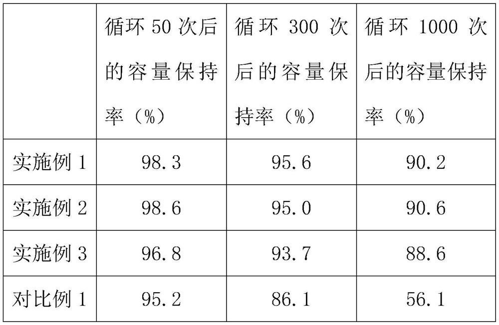
An electroforming method for a high-energy power supply
An electroforming and power supply technology, applied in non-aqueous electrolyte batteries, secondary battery charging/discharging, circuits, etc., can solve the problems of affecting battery cycle life, poor cycle life of electrode materials, and functional failure of battery packs. Stabilize the internal structure of the battery, improve cycle stability and cycle life, and promote the effect of self-improvement
- Summary
- Abstract
- Description
- Claims
- Application Information
AI Technical Summary
Problems solved by technology
Method used
Image
Examples
Embodiment 1
[0042] (1) Charge the battery with a constant current of 0.2C until the battery voltage is 2.7V;
[0043] (2) Stop charging and let it stand for 3 hours;
[0044] (3) Charging at a constant voltage of 2.7V until the charging current becomes below the trickle current, wherein the above-mentioned trickle charging current is 0.03μA;
[0045] (4) Stop charging and let it stand for 2.5 hours;
[0046] (5) Perform square wave AC charging with a square wave AC voltage of 3.3V and a frequency of 35Hz, and the charging time is 2.5 hours;
[0047] (6) Stop charging and let it stand for 5 hours;
[0048] (7) Charge with a constant current of 0.55C until the termination voltage is 4.0V;
[0049] (8) Stop charging and let it stand for 0.5 hours;
[0050] (9) Constant voltage charging with the termination voltage of step (7) until the charging current becomes below the trickle current, wherein the above-mentioned trickle charging current is 0.02 μA;
[0051] (10) Perform square wave AC...
Embodiment 2
[0059] (1) Charge the battery with a constant current of 0.25C until the battery voltage is 2.7V;
[0060] (2) Stop charging and let it stand for 3.5 hours;
[0061] (3) Charging at a constant voltage of 2.7V until the charging current becomes below the trickle current, wherein the above-mentioned trickle charging current is 0.03μA;
[0062] (4) Stop charging and let it stand for 3 hours;
[0063] (5) Perform square wave AC charging with a square wave AC voltage of 3.5V, a current of 0.1C, and a frequency of 50Hz, and the charging time is 3 hours;
[0064] (6) Stop charging and let it stand for 6 hours;
[0065](7) Charge with a constant current of 0.50C until the termination voltage is 4.2V;
[0066] (8) Stop charging and let it stand for 1 hour;
[0067] (9) Constant voltage charging with the termination voltage of step (7) until the charging current becomes below the trickle current, wherein the above-mentioned trickle charging current is 0.02 μA;
[0068] (10) Perform...
Embodiment 3
[0076] (1) Charge the battery with a constant current of 0.3C until the battery voltage is 2.7V;
[0077] (2) Stop charging and let it stand for 5 hours;
[0078] (3) Charging at a constant voltage of 2.7V until the charging current becomes below the trickle current, wherein the above-mentioned trickle charging current is 0.03μA;
[0079] (4) Stop charging and let it stand for 3.5 hours;
[0080] (5) Perform square wave AC charging with a square wave AC voltage of 3.6V and a frequency of 50Hz, and the charging time is 3.5 hours;
[0081] (6) Stop charging and let it stand for 7 hours;
[0082] (7) Charge with a constant current of 0.65C until the termination voltage is 4.2V;
[0083] (8) Stop charging and let it stand for 1.5 hours;
[0084] (9) Constant voltage charging with the termination voltage of step (7) until the charging current becomes below the trickle current, wherein the above-mentioned trickle charging current is 0.02 μA;
[0085] (10) Perform square wave AC...
PUM
 Abstract
Description
Claims
Application Information
 - R&D
- Intellectual Property
- Life Sciences
- Materials
- Tech Scout
- Unparalleled Data Quality
- Higher Quality Content
- 60% Fewer Hallucinations
Browse by: Latest US Patents, China's latest patents, Technical Efficacy Thesaurus, Application Domain, Technology Topic, Popular Technical Reports.
© 2025 PatSnap. All rights reserved.Legal|Privacy policy|Modern Slavery Act Transparency Statement|Sitemap|About US| Contact US: help@patsnap.com

