High-pressure reaction system, and efficient energy recovery feeding and discharging process

A technology of high-pressure reaction and high-pressure reactor, which is applied in the field of high-pressure reaction system and high-efficiency energy recovery material inlet and outlet process, which can solve the problems of valve wear, short service life, and loss of unloading energy, so as to reduce power consumption and avoid high pressure difference Valve wear and the effect of saving power consumption

Pending Publication Date: 2020-01-07
HEBEI UNIVERSITY OF SCIENCE AND TECHNOLOGY +1
View PDF0 Cites 2 Cited by
  • Summary
  • Abstract
  • Description
  • Claims
  • Application Information

AI Technical Summary

Problems solved by technology

[0003] The current high-pressure reaction system mostly uses regulating valves to discharge and adjust the liquid level. The current production process of feeding and discharging materials is to carry out feeding and discharging under high pressure difference, which makes the valve wear seriously, the service life is short, the discharge energy is all lost, and a large amount of energy is generated at the same time. power consumption

Method used


Image

  • High-pressure reaction system, and efficient energy recovery feeding and discharging process
  • High-pressure reaction system, and efficient energy recovery feeding and discharging process
  • High-pressure reaction system, and efficient energy recovery feeding and discharging process

Examples


Embodiment 1

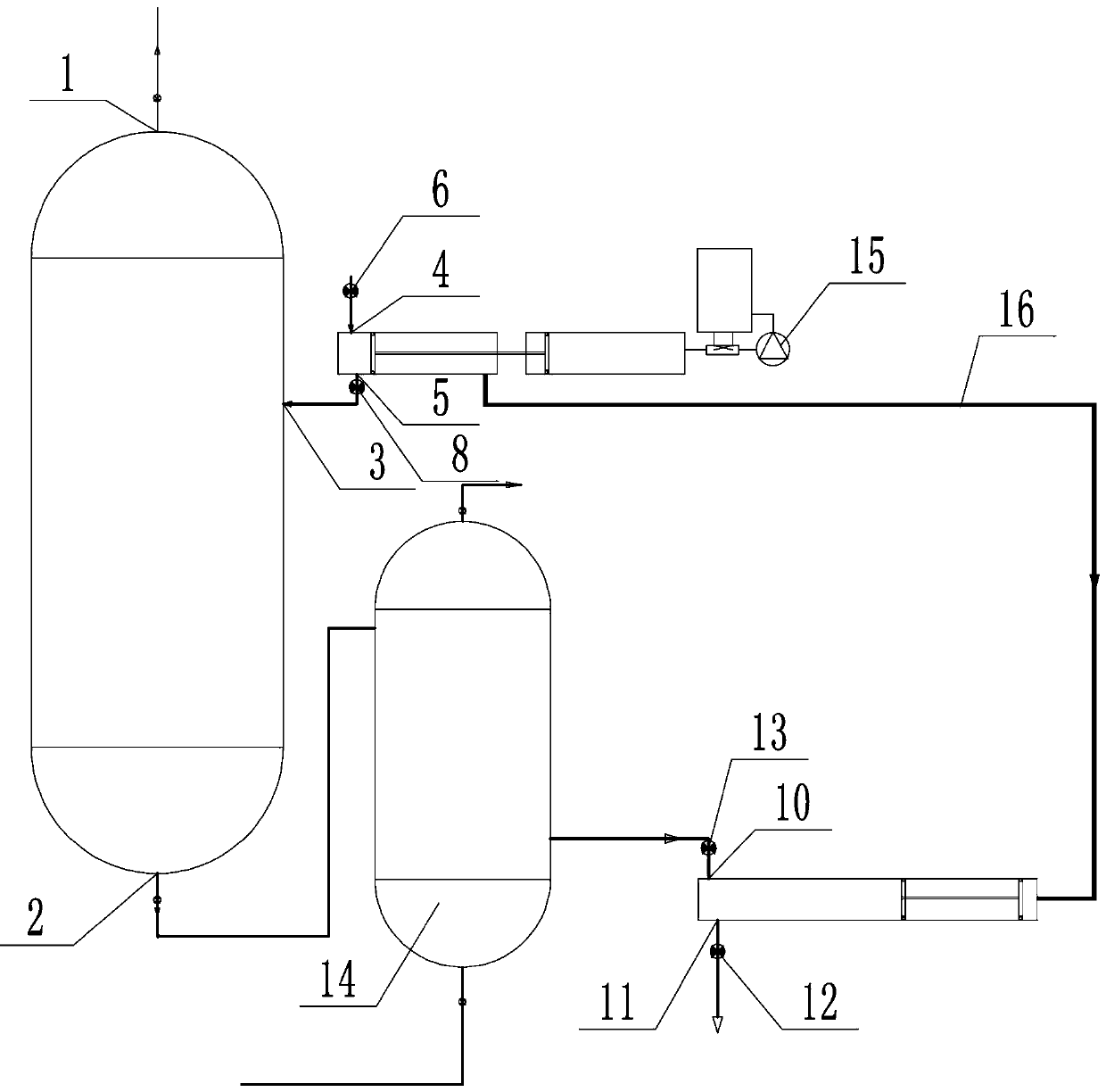
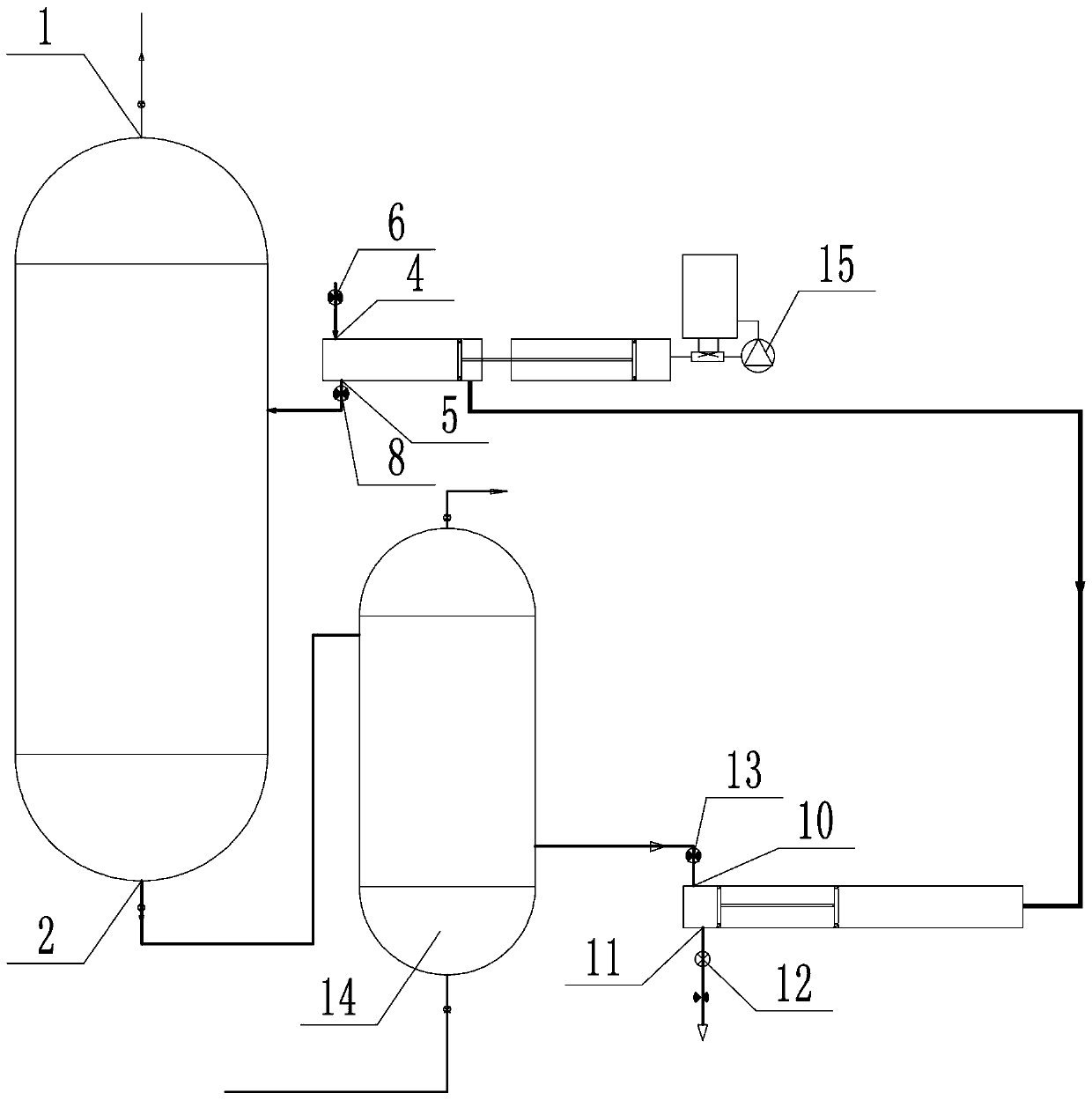
[0036] like Figure 1-2 Shown, the present invention comprises:

[0037] A high-pressure reactor is provided with a first feed port 3 and a liquid phase discharge port 2; the first feed port 3 is located on the side wall of the high-pressure reactor; the optional parameters of the high-pressure reactor are 110-500atm, 200° C- 500°C high pressure reactor. The first feeding port 3 is used to transport the materials in the feeding cylinder into the high pressure reactor.

[0038] Feed cylinder, it comprises the feed cylinder inlet 4 that is provided with first valve 6, the feed cylinder outlet 5 that is connected with described first feed inlet 3, described first feed inlet 3 and inlet A second valve 8 is arranged between the material outlets 5 of the material cylinder; the first valve 6 is used to control the opening and closing of the material inlet 4 of the material cylinder, and the second valve 8 is used to control the opening and closing of the first material inlet 5 .

...

Embodiment 2

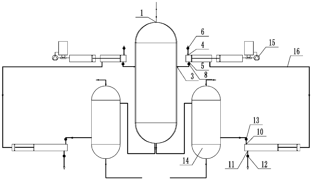
[0066] like Figure 1-3 As shown, the difference between the present embodiment and the high-pressure reaction system of Embodiment 1 is that the quantity of the feed cylinder, the discharge cylinder and the hydraulic pump 15 in the present embodiment is two, one feed cylinder, one discharge cylinder and An oil pressure pump 15 connected with the feeding cylinder is a group of feeding and discharging devices, and a high-pressure reactor is respectively connected with two groups of feeding and discharging devices. As shown in the figure, in this embodiment, two sets of feeding and discharging devices are respectively located on the left and right sides of the high pressure reactor.

[0067] The present invention also provides a high-efficiency energy recovery feed-in and discharge process based on the high-pressure reaction system of the present invention, which includes the following steps,

[0068] The two groups of feeding and discharging devices are respectively the first ...

Embodiment 3

[0076] The difference between this embodiment and Embodiment 2 is that in this embodiment, the gas phase outlet 1 of the high-pressure reactor is connected to the second heat exchanger, and the second heat exchanger is connected to the equipment. The second heat exchanger recovers the energy of the gas phase outlet 1 and provides thermal energy and kinetic energy for the connected equipment. Thus, this embodiment further makes full use of system energy and improves the energy utilization rate.


PUM


Abstract

The invention relates to a high-pressure reaction system. The high-pressure reaction system comprises a high-pressure reactor provided with a first feeding port and a liquid phase discharge port; a feeding cylinder which comprises a feeding cylinder feeding port provided with a first valve, and a feeding cylinder discharging port connected with the first feeding port, wherein a second valve is arranged between the first feeding port and the feeding cylinder discharging port; a discharging cylinder which comprises a second discharging port connected with the liquid phase discharging port and adischarging cylinder discharging port provided with a fourth valve, wherein a third valve is arranged between the liquid phase discharging port and the second discharging port; and an oil hydraulic pump which is connected with the feeding cylinder. According to the high-pressure reaction system, scientific arrangement on valves relating to the feeding cylinder and the discharging cylinder is adopted. The invention also provides efficient energy recovery feeding and discharging process of the high-pressure reaction system; under assisting of pressure provided by the oil hydraulic pump, intermittent feeding and discharging or continuous feeding and discharging are achieved, energy can be fully utilized, the circulation rate of materials in the system can be reduced, and power consumption isreduced.

Description

technical field [0001] The invention relates to the technical field of high-pressure reaction equipment and a material feeding and discharging process, in particular to a high-pressure reaction system and a material feeding and discharging process for high-efficiency energy recovery. Background technique [0002] High-pressure reaction system and high-pressure process equipment are widely used in metallurgy, chemical industry and other industrial production and scientific experiment fields to carry out chemical reactions, such as coal refining, supercritical water coal gasification, petroleum refining, high pressure osmosis reverse osmosis, supercritical water garbage treatment Environmental protection, chemical synthesis, hydrothermal synthesis, plant straw gas production and other fields, such as the application of coal refining reactor at 20-30MPa, the application of high-pressure hydrogenation process of oil refining at 20MPa, and the application of medium-pressure hydrog...

Claims


Application Information

Patent Timeline
Patent Type & Authority Applications(China)
IPC IPC(8): B01J3/02
CPCB01J3/02
Inventor 吴海霞张培杰杨志军
Owner HEBEI UNIVERSITY OF SCIENCE AND TECHNOLOGY
Why Eureka
Try Eureka