
Heat radiating fin antenna array structure

A heat sink and antenna array technology, which is applied in the antenna array, antenna grounding switch structure connection, antenna, etc., can solve the problems of inability to achieve effective heat dissipation and limit the design space of the heat sink, so as to save design cost, reduce design complexity, The effect of saving system space

Active Publication Date: 2020-01-10
SHANGHAI JIAO TONG UNIV
View PDF2 Cites 9 Cited by
  • Summary
  • Abstract
  • Description
  • Claims
  • Application Information

AI Technical Summary

Problems solved by technology

This method can improve the radiation efficiency of the microstrip patch antenna to a certain extent, but since the size of the heat sink base needs to be consistent with the size of the patch, when the operating frequency increases, the size of the patch decreases continuously with the shortening of the wavelength. The design space of the heat sink is greatly limited, resulting in the inability to achieve effective heat dissipation
The above problems are especially acute for mmWave antenna designs

Method used


Image

  • Heat radiating fin antenna array structure
  • Heat radiating fin antenna array structure
  • Heat radiating fin antenna array structure

Examples


Embodiment Construction

[0032] The present invention will be described in detail below in conjunction with the accompanying drawings and specific embodiments. This embodiment is carried out on the premise of the technical solution of the present invention, and detailed implementation and specific operation process are given, but the protection scope of the present invention is not limited to the following embodiments.

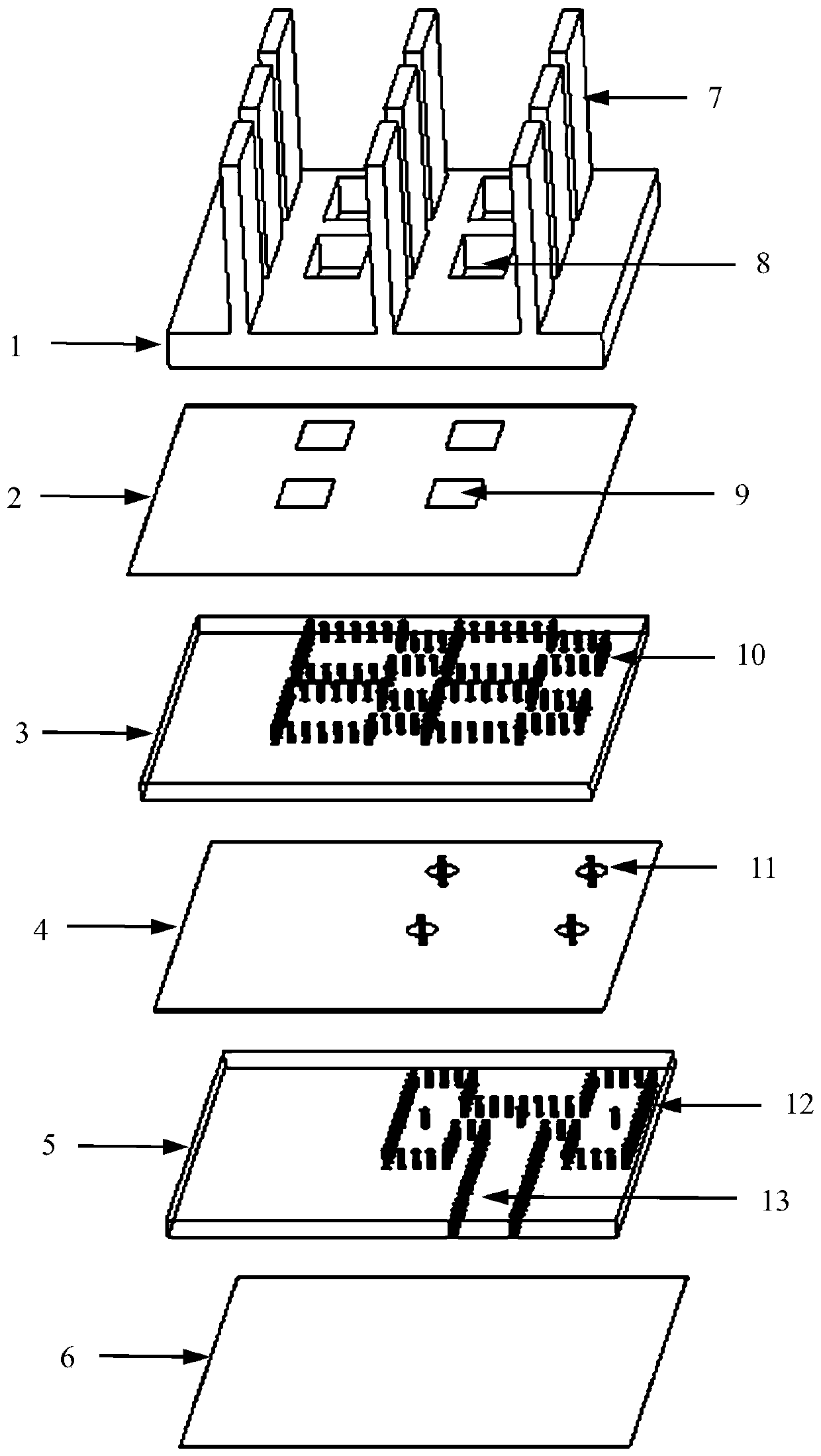
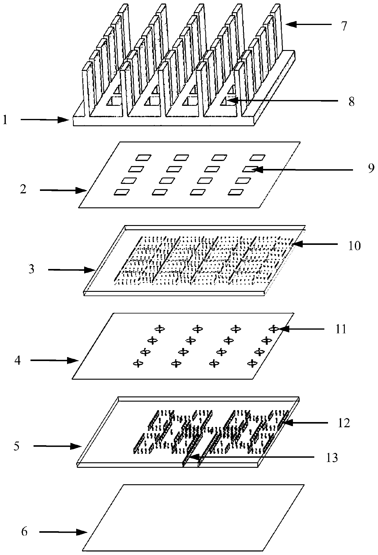
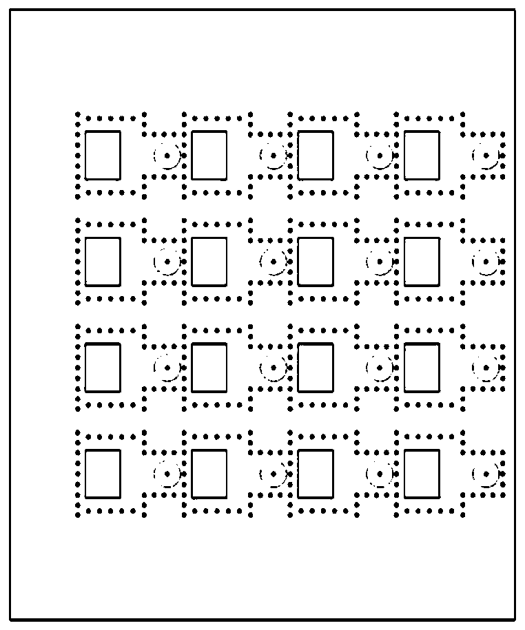
[0033] A heat sink antenna array structure, including a finned metal heat sink 7, a heat sink metal base 1 and a substrate, the substrate is a low-temperature co-fired ceramic substrate, the upper surface of the substrate is connected to the heat sink metal base 1, and the lower surface is connected to a heat source The chips are connected, and the heat sink metal base 1 is provided with a rectangular through-cavity array 8 as an antenna radiation aperture. The rectangular through cavity array 8 of the base corresponds to the rectangular hole array 9, and the dielectric layer contains...


PUM


Abstract

The invention relates to a heat radiating fin antenna array structure which comprises a fin-type metal heat radiating fin, a heat radiating fin metal base and a substrate. The upper surface of the substrate is connected with the heat radiating fin metal base, and the lower surface of the substrate is connected with a heat source chip. The heat radiating fin metal base is provided with a rectangular through cavity array as an antenna radiation caliber. The substrate comprises a plurality of metal layers, a dielectric layer is arranged between the metal layers, and the uppermost metal layer is provided with a rectangular hole array corresponding to the rectangular through cavity array of the heat radiating fin metal base. The dielectric layer includes a metal through hole array used for forming a substrate integrated waveguide structure. The metal through hole array effectively reduces the channel thermal resistance between the fin-type metal heat radiating fin and the heat source chip,and forms the substrate integrated waveguide structure as the feed network of the heat radiating fin antenna. Compared with the structures in the prior art, the conformal structure of the antenna andthe heat radiating fin structure is realized and the integration level of the system is improved.

Description

technical field [0001] The invention relates to the technical field of antennas, in particular to a heat sink antenna array structure. Background technique [0002] With the continuous development of electronic communication technology, the application fields of miniaturized and highly integrated wireless communication systems are becoming more and more extensive. In the process of system design, in order to make full use of space resources and reduce energy loss caused by excessively long feeders, various active and passive devices including chips, front-end circuits and antennas are required to be integrated in a limited-sized package middle. At this time, although the total input power of the system is reduced, due to the reduction of the overall size, the thermal power per unit volume increases instead, which can easily cause the performance of the device to decrease, resulting in the system not working normally or even seriously damaged. . Therefore, in the actual de...

Claims


Application Information

Patent Timeline
Patent Type & Authority Applications(China)
IPC IPC(8): H01Q1/00H01Q1/38H01Q1/50H01Q13/02H01Q21/06
CPCH01Q1/02H01Q1/38H01Q1/50H01Q13/02H01Q21/064H01P3/121
Inventor 唐旻钱佳唯张跃平毛军发
Owner SHANGHAI JIAO TONG UNIV
Learn More