Fluoroscopic imaging system

A technology of imaging and irradiation methods, which is applied to the components of TV systems, TVs, color TVs, etc., and can solve problems such as difficult technical operations and long time

Inactive Publication Date: 2003-04-30
SHIMADZU SEISAKUSHO CO LTD
View PDF7 Cites 0 Cited by
  • Summary
  • Abstract
  • Description
  • Claims
  • Application Information

AI Technical Summary

Problems solved by technology

[0004] The technical operation required by IVR is usually not easy, so the time taken for fluoroscopy images is generally longer (sometimes up to several times the time of ordinary angiography), so that the X-ray fluoroscopy dose to the patient is a problem

Method used


Image

  • Fluoroscopic imaging system
  • Fluoroscopic imaging system
  • Fluoroscopic imaging system

Examples


Embodiment Construction

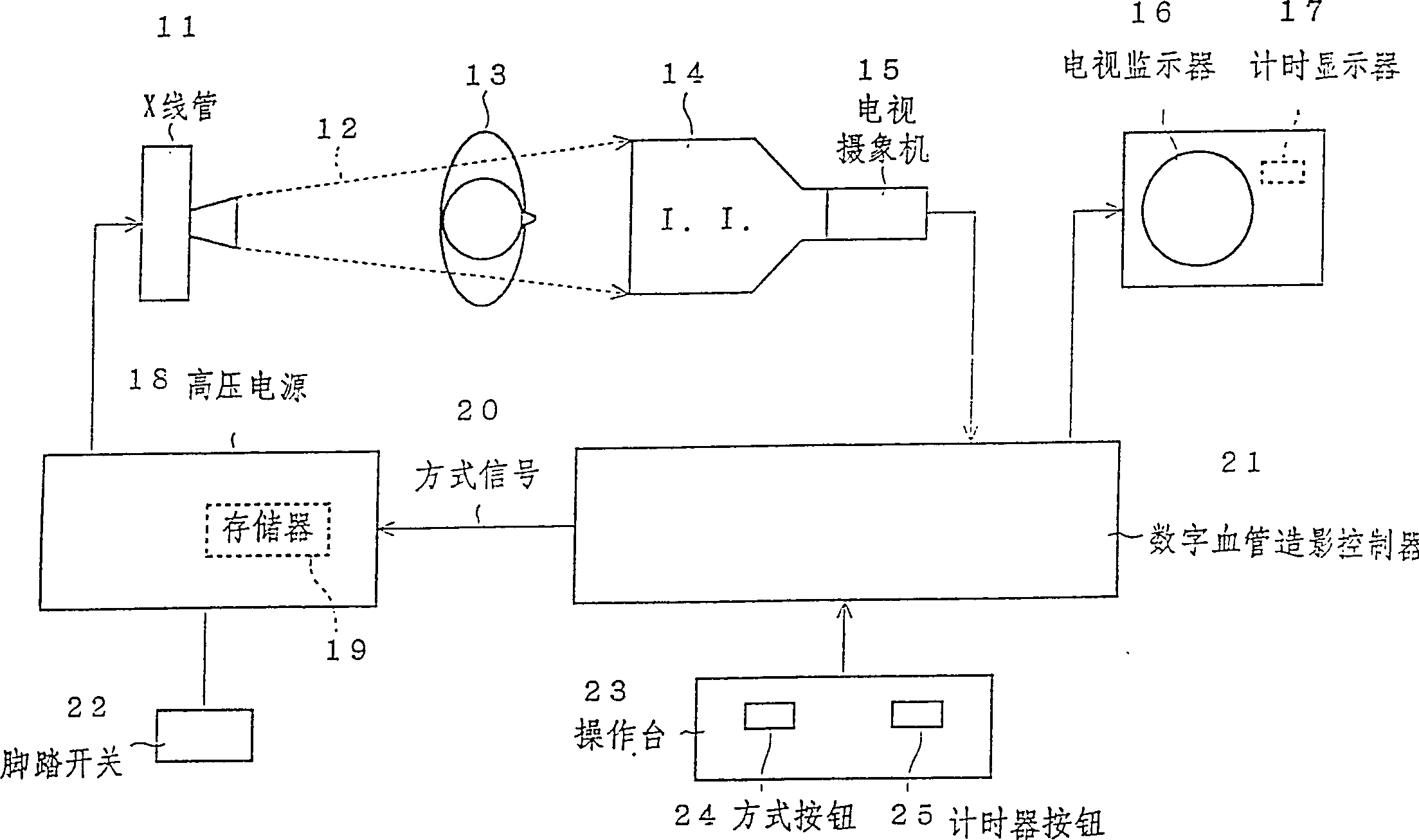
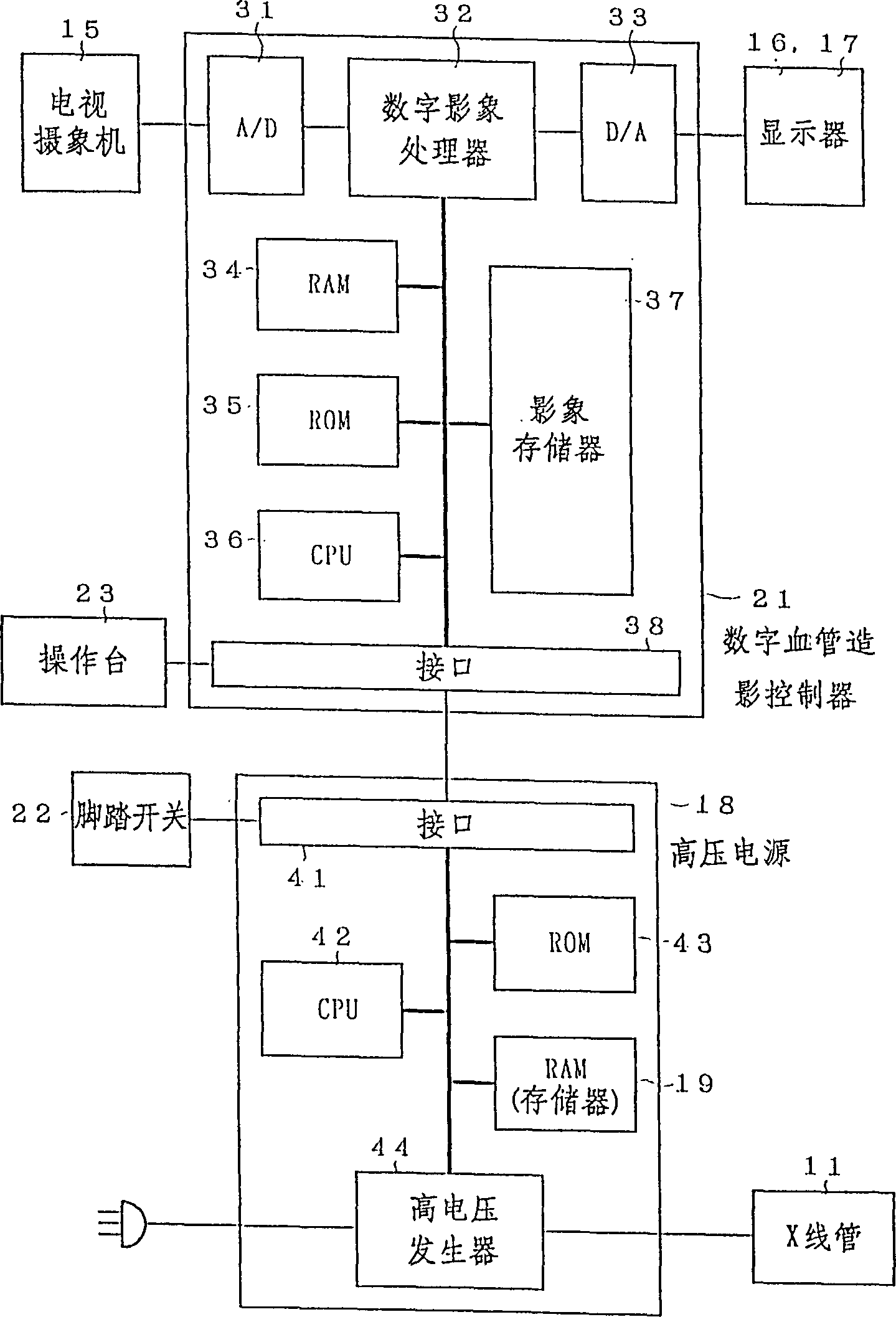
[0018] see Figures 1 to 5C A preferred embodiment of the present invention is described. figure 1 In the process, the X-ray tube 11 receives a high voltage from a high-voltage power supply 18 and irradiates an X-ray beam 12 onto an object 13 . The X-rays passing through the object 13 enter an image intensifier (I.I., image intensifier) ​​14 to form an X-ray image on a display screen, which is then captured by a television camera 15 . The video signal of the X-ray image that television camera 15 produces is sent to digital angiography controller 21, figure 2 The controller is shown in detail.

[0019] The analog video signal from the television camera 15 is first converted into digital image data in the analog / digital converter (A / D) 31, and then in the digital image processor 32, various images are performed on the X-ray image data. Processing (for example, noise filtering or edge enhancement, etc.). The processed image data is converted into an analog video signal again...


PUM


Abstract

In an interventional radiography (IVR), for example in a percutaneous transluminal coronary angioplasty (PTCA), when the IVR includes a period in which the movement of the object is slow, a normal X-ray radiating mode (a continuous X-ray radiation or a normal rate pulse radiation of about 15-30 pulses per second) is changed to a very slow rate pulse X-ray radiation of about 1-5 pulses per second to decrease the X-ray dose of the patient. Since the movement is slow, the very slow rate pulse radiation can still trace the movement adequately. Further, the quality of the X-ray image is improved by increasing the tube current in the very slow rate pulse radiation because less heat is generated in the X-ray tube.

Description

technical field [0001] The present invention relates to a perspective image system used in medical diagnosis or treatment. Background technique [0002] The fluoroscopic image system provides real-time X-ray images of the appropriate parts of the subject or patient on a monitor using a television system. This technology is widely used in various clinical fields, including angiography or interventional X-ray photography (IVR, interventioni-onal radiography), etc. One of IVR is called percutaneous transluminal coronary angioplasty (PTCA, Percutaneous transluminal coronary angioplasty). [0003] PTCA is to insert the catheter into the patient's circulatory system towards the heart, put the inflatable balloon at the end of the catheter into the stenosis of the coronary artery, and then inflate the balloon several times to treat the stenosis. The guiding operation of the balloon catheter in the circulatory system and the inflation operation of the balloon in the stenosis are ca...

Claims


Application Information

Patent Timeline
Patent Type & Authority Patents(China)
IPC IPC(8): A61B6/00H04N5/32H05G1/30H05G1/60
CPCH04N5/3205H05G1/30H05G1/60
Inventor 铃木英文
Owner SHIMADZU SEISAKUSHO CO LTD
Why Eureka
Try Eureka