In-situ sludge recycling system device

A system device and in-situ technology, applied in water/sludge/sewage treatment, dehydration/drying/thickened sludge treatment, water pollutants, etc., can solve the problem of difficult odor tail gas, high fuel cost, poor activity, etc. problem, to achieve the effect of efficient, sustainable and controllable production time

Active Publication Date: 2020-01-17
ATK HLDG GRP CO LTD +1
View PDF6 Cites 2 Cited by
  • Summary
  • Abstract
  • Description
  • Claims
  • Application Information

AI Technical Summary

Problems solved by technology

Sludge carbonization requires heating. High-temperature carbonization can make the carbonized product have the characteristics of large specific area and pore size and high activity, but the fuel cost is high. Although the medium and low temperature carbonization controls the fuel cost, the specific area and pore size of the carbonized product are small, and the activ

Method used


Image

  • In-situ sludge recycling system device
  • In-situ sludge recycling system device
  • In-situ sludge recycling system device

Examples


Embodiment 1

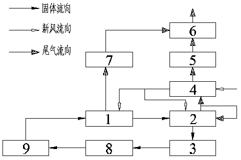
[0040] A sludge in-situ recycling system device, including a vertical unpowered spiral stirring biological drying device 1, a vertical sandless jet flow carbonization furnace 2, a pulverizing vacuum liquefaction device 3, a tail gas wet treatment device 6, and a dust collector 5 , heat exchanger 4, negative pressure device 7;

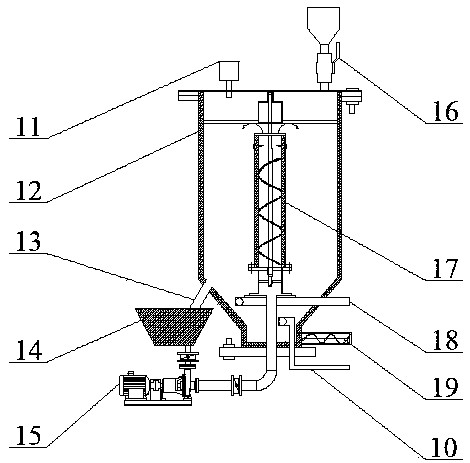
[0041]Vertical non-powered spiral stirring biological drying device 1, including the main body of the drying device and the stirring device; There is a feed inlet 16 and a biological drying outlet 11. The biological drying outlet 11 is connected to the negative pressure device 7. The bottom is conical, and the angle of the cone is designed to be <45°, which is easy to promote the sliding and mixing of sludge. A dried biomass outlet 19 and a liquid discharge port 10 are arranged at the bottom of the cone, an air inlet is provided at the middle of the cone, and an air inlet pipe 18 is arranged inside. One end of the air inlet pipe 18 is connected with the...


PUM


Abstract

The invention relates to the field of environment protection and discloses an in-situ sludge recycling system device which comprises a vertical non-dynamic spiral stirring biological drying device, avertical sandless jet carbonization furnace, a crushing vacuum liquefaction device, a tail gas wet process treatment device, a dust collector, a heat exchanger and a negative pressure device. According to the in-situ sludge recycling system device, sludge is treated by using a technique of biological drying and carbonization energy-saving resource recycling and in-situ recycling, a truly seamlessclosed loop of sludge treatment and disposal is achieved, meanwhile, development of related industries is promoted, and the requirements of "green, recycling and low-carbon" are truly achieved. The technique is a novel comprehensive sludge treatment and disposal system with a high integration degree, and has the technical advantages of being low in operating cost, small in floor space, high in automation degree, simple in operation management, free of secondary pollution, and the like.

Description

technical field [0001] The invention belongs to the field of environmental protection, and in particular relates to a sludge in-situ recycling system device. Background technique [0002] Sludge will inevitably be produced in urban sewage treatment. According to the estimate that sludge accounts for 0.8‰, the daily output of sludge (with a water content of 80%) in the country is about 40 million tons. Due to the high water content, the organic matter of these sludges The content is low and the total calorific value is not high, which brings great difficulties to recycling. At present, many technologies and equipment have been developed on how to reduce the water content in sludge, such as high-pressure plate and frame filter technology, heat pump technology, thin-layer thermal drying technology, rotary kiln drying technology, etc., but these technologies only realize sludge reduction purpose. Therefore, based on the above-mentioned high-efficiency dehydration technology, a...

Claims


Application Information

Patent Timeline
IPC IPC(8): C02F11/13C10B57/10C10B53/00C10B57/04C10B1/04B01J20/20B01J20/30C02F3/00C02F3/34C02F101/30
CPCB01J20/20C02F3/00C02F3/104C02F3/106C02F3/34C02F2003/001C02F2003/003C02F2101/30C02F2209/08C10B1/04C10B53/00C10B57/04C10B57/10C02F11/13
Inventor 吴智仁徐畅蒋素英刘志刚泽井正和
Owner ATK HLDG GRP CO LTD
Why Eureka
Try Eureka