Three-layer all-dielectric rectangular grating for realizing -2 level broadband high efficiency

A rectangular grating, all-dielectric technology, applied in the field of three-layer all-dielectric rectangular grating, to achieve the effects of mature technology, small aspect ratio and low cost

Active Publication Date: 2020-01-21
SHANGHAI INST OF OPTICS & FINE MECHANICS CHINESE ACAD OF SCI
View PDF3 Cites 2 Cited by
  • Summary
  • Abstract
  • Description
  • Claims
  • Application Information

AI Technical Summary

Problems solved by technology

No one has yet designed a high-efficiency diffraction grating for a transmissive multilayer dielectric rectangular grating

Method used


Image

  • Three-layer all-dielectric rectangular grating for realizing -2 level broadband high efficiency
  • Three-layer all-dielectric rectangular grating for realizing -2 level broadband high efficiency
  • Three-layer all-dielectric rectangular grating for realizing -2 level broadband high efficiency

Examples


specific Embodiment approach 1

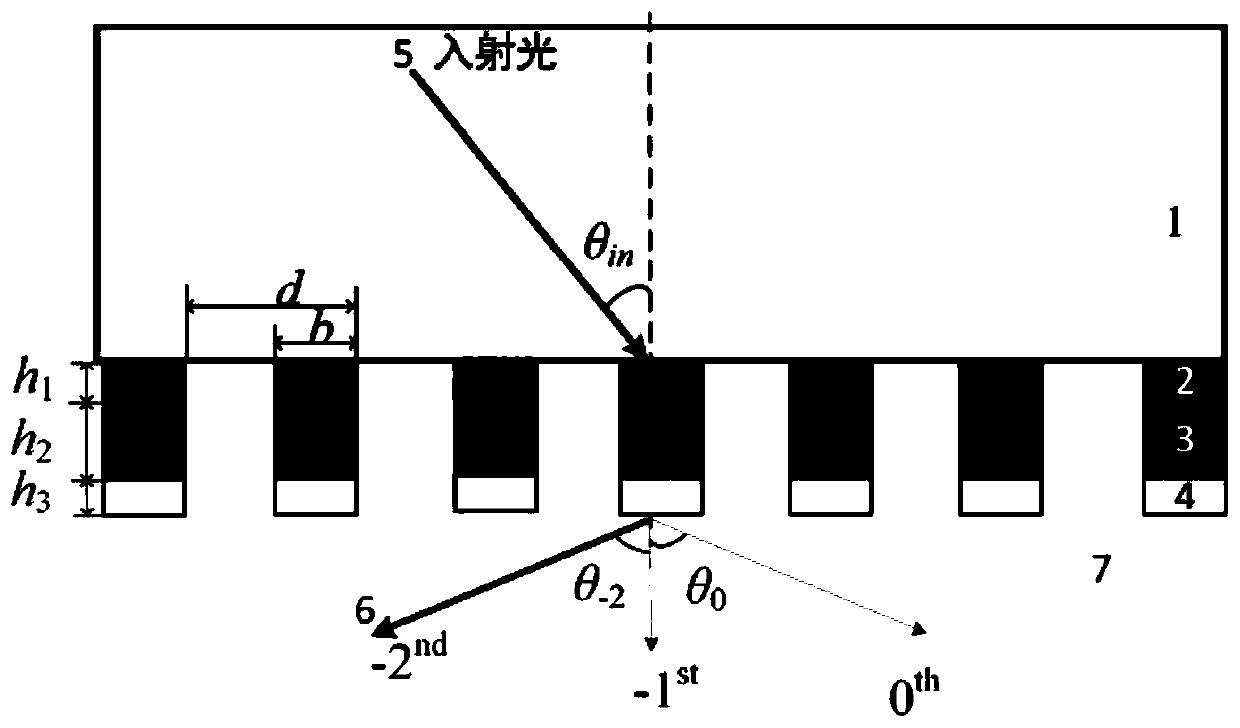
[0034] see first figure 1 , figure 1 It is a schematic diagram of a negative secondary high-efficiency three-layer all-dielectric rectangular grating in the 1.5 micron band of the present invention, in the figure: θ in represents the angle of incidence, θ -2 , θ 0 are the diffraction angles of -2 order and 0 order respectively, h 1 、h 2 and h 3 are the layer thicknesses of aluminum oxide, titanium dioxide and silicon dioxide in the three-layer all-dielectric rectangular grating structure, respectively. b represents the width of the grating ridge, and d represents the grating period (the duty cycle is f=b / d). Areas 1, 2, 3, 4, and 7 are homogeneous media. The grating vector K is located in the incident plane, the vibration direction of the TE polarized light corresponding to the electric field vector is perpendicular to the incident plane, and the TE polarized light is at a certain angle θ in =arcsin(λ / n 1 d) (defined as the quadratic Bragg angle) incident on the grati...

specific Embodiment approach 2

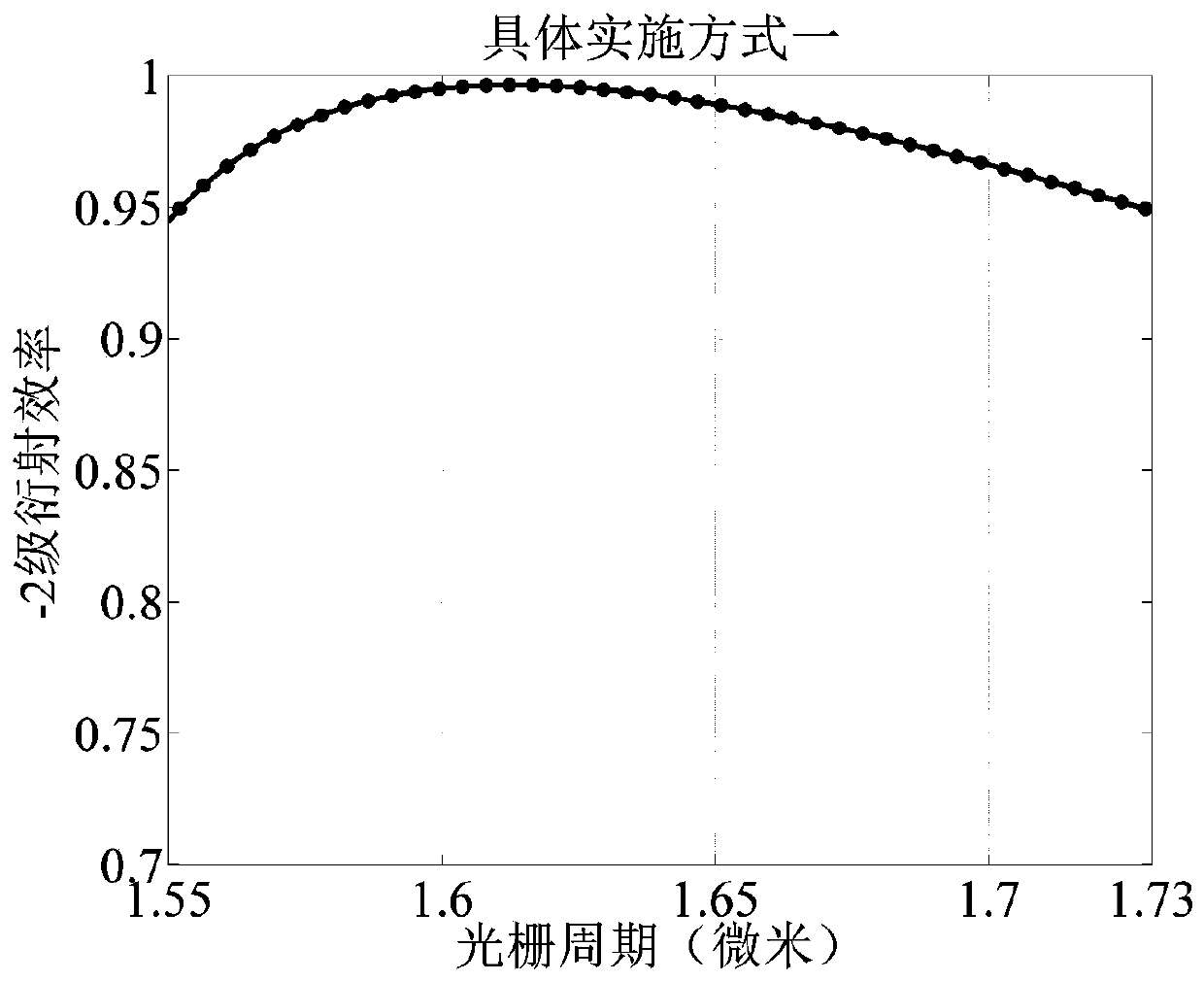
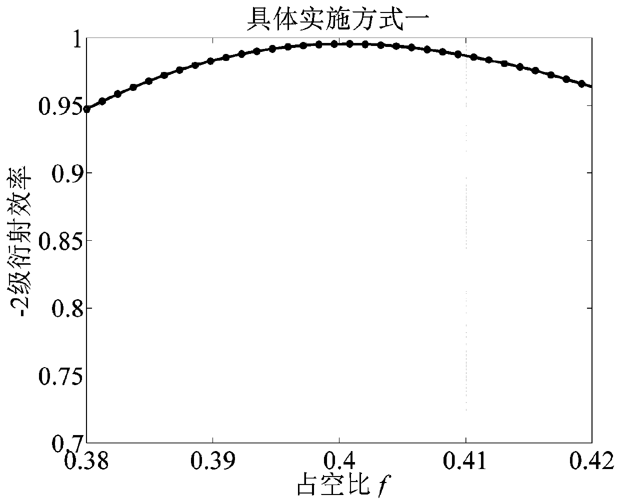
[0038] Due to different wavelengths, the corresponding refractive index of the material is also different. The three-layer structure is re-optimized below, and the grating structure is still used figure 1 Structure, re-optimize the structural parameters, when the grating duty cycle is 0.4263, the period is 0.8647 microns, and the depth h 1 184.2 nm, h 2 506 nm, h 3 When it is 186.1 nanometers, the effect is the best. Figure 9 , Figure 10 , Figure 11 , Figure 12 with Figure 13 , are the control variables for the duty cycle, duty cycle f, h1, h2, and h3 respectively, and study the influence of its tolerance on the value of the -2 order diffraction efficiency. It can be seen that for each parameter variable, the diffraction efficiency output of more than 95% can be achieved within a large tolerance range. For the diffraction efficiency above 95% is the standard, the tolerance intervals are, period (833.9-924.2 nanometers), duty cycle (0.4076-0.4494), h1 (113.9-257.9 n...


PUM

PropertyMeasurementUnit
depthaaaaaaaaaa
refractive indexaaaaaaaaaa

Abstract

A three-layer all-dielectric rectangular grating for realizing -2 level broadband high efficiency comprises fused silica as a medium of an incident area and a grating ridge as a three-layer all-dielectric rectangular grating which comprises a first layer of alumina, a second layer of titanium dioxide and a third layer of fused silica, characterized in that in the three-layer rectangular grating, the refractive index of a middle layer is largest, and the refractive index of each layer of material is between the refractive indexes of two adjacent materials. Femtosecond laser light is incident ata secondary Bragg angle theta in=arcsin (gamma/n1d). n1 is the refractive index of the incident area, d represents a grating period, and b represents the width of the grating ridge. The rectangular grating of the present invention can achieve that transmission -2 level diffraction efficiency is close to 1 for TE polarized light. The grating has the characteristics of simple structure, rectangularstructure, small depth-to-width ratio, easy processing and large manufacturing tolerance. The grating is easily realized under a microelectronic deep etching process which combines a current opticalholographic recording technology or an electron beam direct writing technology, is mature in process, low in cost and capable of realizing batch production, and has important application prospects.

Description

technical field [0001] The invention relates to a broadband high-efficiency grating, in particular to a three-layer all-dielectric rectangular grating realizing -2-level broadband high efficiency. Background technique [0002] In the field of femtosecond lasers, spectroscopic devices such as prisms cannot be used due to the introduction of material dispersion. The grating can not only separate the spectrum, but also compensate the dispersion. It has the advantages of compensating dispersion, compact structure, high efficiency, and easy fabrication. It is the most important optical device in the femtosecond laser field. The all-dielectric rectangular grating has a higher damage threshold than the gold-plated grating, so the all-dielectric grating has important practical prospects. [0003] The all-dielectric rectangular grating is easy to manufacture, and can be processed by one-time exposure, development, etching and other conventional processes in the holographic interfere...

Claims


Application Information

Patent Timeline
Patent Type & Authority Applications(China)
IPC IPC(8): G02B5/18
CPCG02B5/1809
Inventor 周常河尹正坤余俊杰鲁云开
Owner SHANGHAI INST OF OPTICS & FINE MECHANICS CHINESE ACAD OF SCI
Why Eureka
Try Eureka