High-speed wavelength tuning laser made of lithium niobate material

A lithium niobate and laser technology, applied in the field of high-speed wavelength tuning lasers, can solve the problems of unsatisfactory electro-optic effect, and achieve the effect of fast response speed and fast wavelength tuning

Active Publication Date: 2020-01-24
ZHEJIANG UNIV
View PDF12 Cites 11 Cited by
  • Summary
  • Abstract
  • Description
  • Claims
  • Application Information

AI Technical Summary

Problems solved by technology

Although other photonic platforms have been put into good use,

Method used


Image

  • High-speed wavelength tuning laser made of lithium niobate material
  • High-speed wavelength tuning laser made of lithium niobate material
  • High-speed wavelength tuning laser made of lithium niobate material

Examples


Embodiment Construction

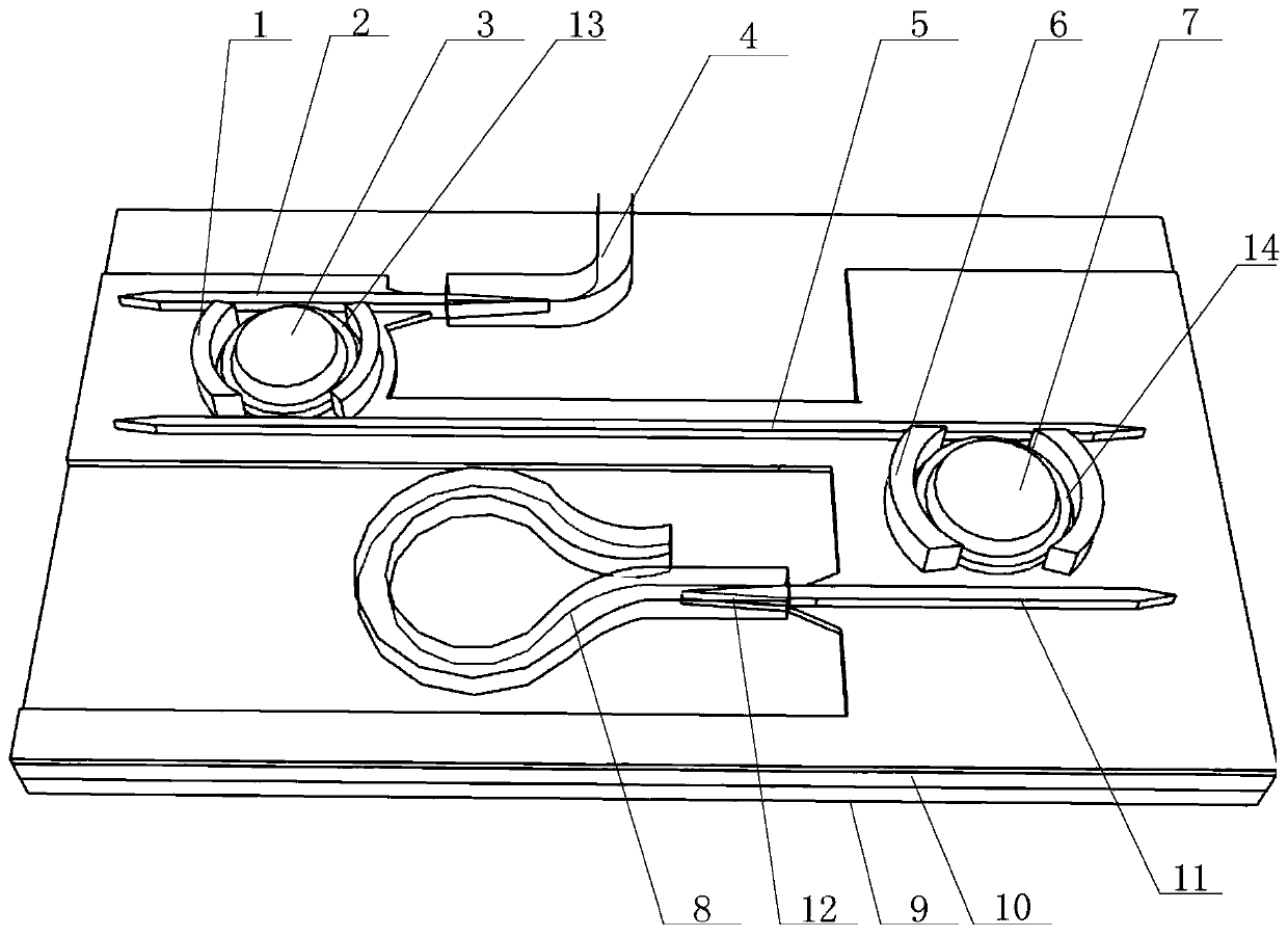
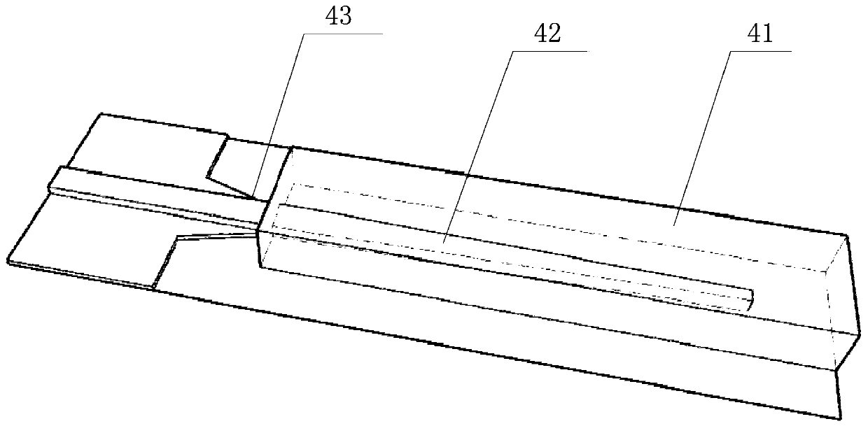
[0041] Such as figure 1 As shown, a high-speed wavelength-tunable laser made of lithium niobate material includes: a lithium niobate thin film chip (that is, an LNOI chip); a first mode spot converter 4 (SSC , spot sizeconverter); the composite resonant cavity connected to the first mode spot converter 4, the composite resonant cavity is made of lithium niobate material. Lithium niobate thin film chip comprises silicon substrate 9, the SiO that arranges silicon substrate 9 2 Buried oxide layer 10 and set on SiO 2 The lithium niobate thin film on the buried oxide layer 10 (that is, the lithium niobate film with a thickness of 10-999 nm).

[0042] The compound resonant cavity comprises: the input end waveguide 2 that is connected with the mode spot converter 4; The first ring resonator 13 that is coupled and connected with the input end waveguide 2; The cascade waveguide 5 that is coupled and connected with the first ring resonant cavity 13 (for light output); the second ring...


PUM


Abstract

The invention discloses a high-speed wavelength tuning laser made of lithium niobate material. The laser comprises a lithium niobate thin film chip (i.e. LNOI chip); a first spot size converter (SSC)arranged on the lithium niobate thin film chip; and a composite resonant cavity connected with the first spot size converter, wherein the composite resonant cavity adopts the lithium niobate material.The composite resonant cavity adopts the lithium niobate material and has good electro-optic effect. The electro-optic coefficient r33 of the X-cut lithium niobate thin film can reach 30.8 pm/V whenthe optical mode propagates along the y direction and the electric field direction is the z direction. The wavelength tuning speed of the laser can reach ns level and the tuning range can be more than10nm so that the laser can be used in an optical switching network to reduce network congestion and enable information transmission to be faster.

Description

technical field [0001] The invention relates to the technical field of lasers with high-speed wavelength tuning, in particular to a laser with high-speed wavelength tuning made of lithium niobate material. Background technique [0002] Most of the wavelength tunable lasers currently on the market are based on InP materials, such as distributed Bragg grating array lasers (DFB array) and vertical cavity surface emitting lasers (Vertical Cavity Surface Emitting Laser). To reduce the cost and power consumption of photonic devices, one often needs to shrink the device size and manufacture it using redesigned and low-cost processes. A typical scheme for realizing such an integrated optically coherent light source is a silicon-based photonic waveguide system, which is a good platform for monolithic integration due to its large wafer size, low-cost materials, and use of fabrication processes and equipment derived from electronics. [0003] With the rapid development of digital netw...

Claims


Application Information

Patent Timeline
IPC IPC(8): H01S5/10
CPCH01S5/1028H01S5/1042
Inventor 储涛刘晨
Owner ZHEJIANG UNIV
Why Eureka
Try Eureka