
Hardware modular control and drive integrated device

A hardware module, integrated technology, applied in electrical components, control systems, motor control and other directions, can solve the problem of affecting the response speed of interpolation points, unable to complete the high requirements of trajectory accuracy and speed, and limited robot trajectory accuracy and response speed.

Active Publication Date: 2020-02-07
FOSHAN INST OF INTELLIGENT EQUIP TECH
View PDF8 Cites 0 Cited by
  • Summary
  • Abstract
  • Description
  • Claims
  • Application Information

AI Technical Summary

Problems solved by technology

[0003] Until the advent of the era of industrial robots, unlike traditional machine tools, although the "controller + driver" method can provide real-time multi-axis linkage control for robots, this linkage is due to the data exchange between the controller and the driver through the serial bus. The system can only achieve millisecond-level motion control, which will encounter bottlenecks in some high-speed and high-precision occasions
In addition, the robot is a nonlinear time-varying system, and its motion process is always subjected to external forces including gravity and friction. The force is always changing in different postures. According to the traditional "controller + driver" form , each axis of the driver will work independently in the position servo mode, and the change of the external force will affect the response speed of its interpolation point, resulting in the limitation of the overall trajectory accuracy and response speed of the robot, and thus the scene with high trajectory accuracy and high speed requirements cannot be completed.

Method used


Image

  • Hardware modular control and drive integrated device
  • Hardware modular control and drive integrated device

Examples


Embodiment 1

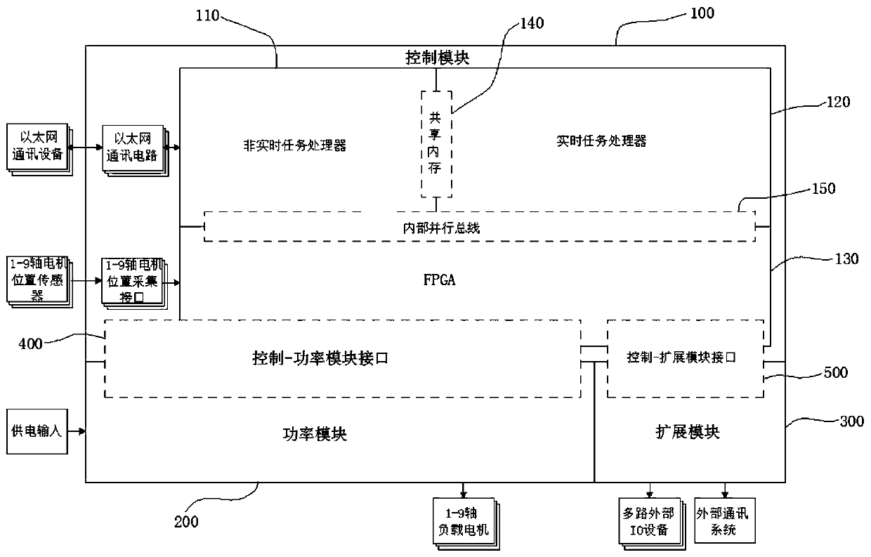
[0019] Such as figure 1 As shown, the hardware modular control-drive integrated device of this embodiment includes a control module 100, a power module 200 and an expansion module 300, and a control-power module interface 400 is provided between the control module 100 and the power module 200, and the control -The power module interface 400 realizes the data exchange between the control module 100 and the power module 200, and the control-expansion module interface 500 is arranged between the control module 100 and the expansion module 300, and the control-expansion module interface 500 realizes the control module 100 and the expansion module The data exchange of module 300; Described control module 100 also comprises non-real-time task processor 110, real-time task processor 120 and FPGA array 130, realizes by shared memory 140 between non-real-time task processor 110 and real-time task processor 120 For data exchange, the non-real-time task processor 110, the real-time task ...

Embodiment 2

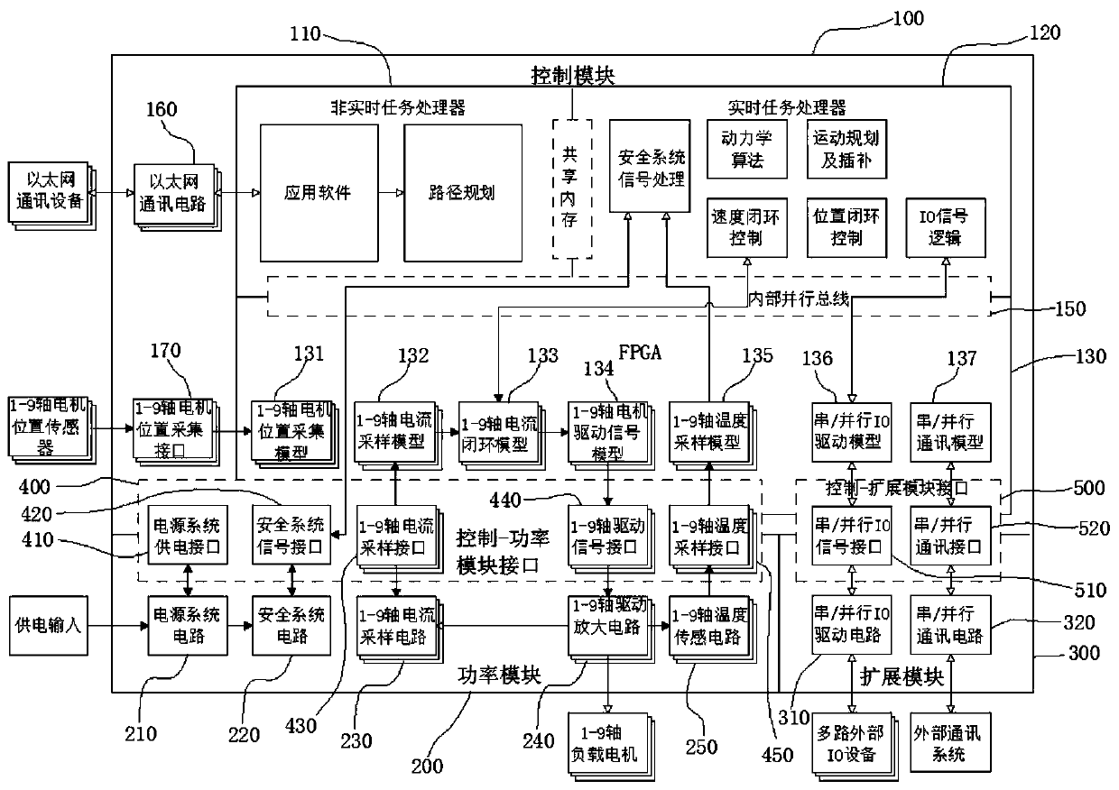
[0021] Such as figure 1 , 2 As shown, the non-real-time task processor 110 carries application software and performs path planning, and the real-time task processor 120 runs dynamics algorithms, motion planning and interpolation, position closed-loop control, speed closed-loop control, safety system signals and IO signals logic. The FPGA array 130 includes a 1-9 axis motor position acquisition model 131, a 1-9 axis current sampling model 132, a 1-9 axis current closed-loop model 133, a 1-9 axis motor drive signal model 134, and a 1-9 axis temperature sampling model 135 , serial / parallel IO drive model 136 and serial / parallel communication model 137, the serial / parallel IO drive model 136 performs signal interaction with the IO signal logic output by the real-time task processor 120, the 1-9 axis motor drive signal model 134 and the speed closed loop Controls signal interactions. The non-real-time task processor 110 and the real-time task processor 120 run the robot closed-l...

Embodiment 3

[0023] Such as figure 1 , 2 As shown, the control-expansion module interface 500 includes a serial / parallel IO signal interface 510 and a serial / parallel communication interface 520, and the expansion module 300 includes a serial / parallel IO drive circuit 310 and a serial / parallel communication circuit 320, and the serial / parallel IO signal interface 510 is respectively connected to the serial / parallel IO driver model 136 and the serial / parallel IO driver circuit 310 , and the serial / parallel communication interface 520 is respectively connected to the serial / parallel communication model 137 and the serial / parallel communication circuit 320 . Control-power module interface 400 includes power system power supply interface 410, safety system signal interface 420, 1-9 axis current sampling interface 430, 1-9 axis drive signal interface 440, 1-9 axis temperature sampling interface 450; 1-9 axis The temperature sampling interface 450 is connected with the 1-9 axis temperature samp...


PUM


Abstract

The invention relates to the field of control systems, in particular to a hardware modular control and drive integrated device. A control module, an expansion module and a power module are integratedin a hardware modular mode, so that the purpose of control and drive integrated efficient integration is achieved, and the advantage of control and drive integrated efficient integration is embodied.According to different application scenarios, the purpose of high efficiency and flexibility is achieved by replacing adaptive hardware modules, and the limitation of application of the control and drive integrated system is avoided. A control mode of a traditional controller and a driver is abandoned, control and driving are integrated in the same module, and millisecond-level motion control is broken through. By means of the hardware modularization mode, stepped control over hardware cost can be achieved. A control and drive integrated system is built by using a standard module with optimized cost in a conventional application scene, and a targeted control and drive integrated system can be built by replacing an adaptive module in a complex application scene, so that cost control for theapplication scene is achieved.

Description

【Technical field】 [0001] The invention relates to the field of control systems, in particular to a hardware modular control-drive integrated device. 【Background technique】 [0002] In the past two decades, due to the strong industrial demand for general-purpose machine tools and special-purpose equipment, the controllers, drivers, user interfaces, and application software developed by suppliers of industrial control system components are based on an independent, multi-functional, multi-occasion Compatible design, this kind of freely combinable and flexible design, can meet the needs of users to quickly implement a relatively reliable control system for the machine to a certain extent. [0003] Until the advent of the era of industrial robots, unlike traditional machine tools, although the "controller + driver" method can provide real-time multi-axis linkage control for robots, this linkage is due to the data exchange between the controller and the driver through the serial b...

Claims


Application Information

Patent Timeline
IPC IPC(8): H02P29/00H02P5/00
CPCH02P29/00H02P5/00
Inventor 陈思敏夏亮招子安周星朱明周伟娜
Owner FOSHAN INST OF INTELLIGENT EQUIP TECH
Learn More