Vacuum welding device and method of amorphous alloy

A vacuum welding and amorphous alloy technology, which is applied in welding equipment, laser welding equipment, metal processing equipment, etc., can solve the problems of reducing the ability of materials to form amorphous, insufficient welding penetration, and reducing the quality of weld formation

Pending Publication Date: 2020-02-11
CHINA-UKRAINE INST OF WELDING GUANGDONG ACAD OF SCI
View PDF6 Cites 7 Cited by
  • Summary
  • Abstract
  • Description
  • Claims
  • Application Information

AI Technical Summary

Problems solved by technology

However, there are still the following problems in the welding process of amorphous alloys: 1) zirconium-based, magnesium-based, titanium-based, aluminum-based and other amorphous alloys are prone to oxidation during welding, and the incorporation of O atoms will reduce the formation of amorphous materials. Ability, resulting in the crystallization of welded joints and the decline in mechanical properties
In addition, the oxidation of the joint will also lead to the formation of a black oxide film on the surface of the weld, and the appearance of the weld is not good
2) Laser welding in an atmospheric pressure environment will generate a large amount of plasma, which hinders the absorption of laser light by the workpiece to be welded, reduces the penetration depth, and the obtained amorphous alloy weld will also have defects such as pores and undercuts, which will reduce the formation of the weld. quality
However, as outlined in the above-mentioned patent, the existing amorphous alloy laser welding technology still has problems such as joint oxidation, weld surface defects, and insufficient welding penetration, which need to be further resolved

Method used


Image

  • Vacuum welding device and method of amorphous alloy
  • Vacuum welding device and method of amorphous alloy
  • Vacuum welding device and method of amorphous alloy

Examples


Embodiment Construction

[0046] In order to make the purpose, technical solutions and advantages of the embodiments of the present invention clearer, the technical solutions in the embodiments of the present invention will be clearly and completely described below in conjunction with the drawings in the embodiments of the present invention. Obviously, the described embodiments It is a part of embodiments of the present invention, but not all embodiments. The components of the embodiments of the invention generally described and illustrated in the figures herein may be arranged and designed in a variety of different configurations.

[0047] Accordingly, the following detailed description of the embodiments of the invention provided in the accompanying drawings is not intended to limit the scope of the claimed invention, but merely represents selected embodiments of the invention. Based on the embodiments of the present invention, all other embodiments obtained by persons of ordinary skill in the art wi...


PUM


Abstract

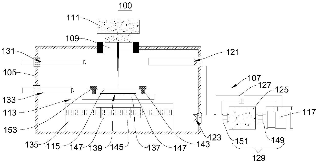
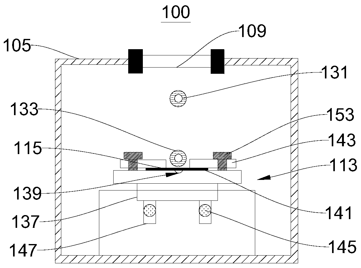
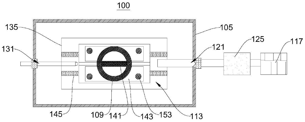
The invention discloses a vacuum welding device and method of amorphous alloy and relates to the technical field of welding. The vacuum welding device of the amorphous alloy comprises a vacuum mechanism and a welding mechanism. The vacuum mechanism comprises a vacuum cavity and a vacuum assembly arranged in the vacuum cavity and used for conducting vacuumizing treatment on the vacuum cavity. An optical lens is embedded on the vacuum cavity. The welding mechanism comprises a laser device and a welding assembly. The laser device is arranged outside the vacuum cavity. An emission opening of the laser device is opposite to the optical lens. The welding assembly is arranged in the vacuum cavity. The welding assembly is provided with a welding platform used for holding to-be-welded pieces. The welding platform is opposite to the optical lens. By means of arrangement of the vacuum mechanism and the welding mechanism, the vacuum welding device can adopt the vacuum laser welding technology to weld the amorphous alloy in the vacuum environment, so that the joint oxidation problem can be effectively solved; the weld penetration depth can be increased beneficially, the width of a weld seam isreduced, the probability of air pores, undercut and other defects are reduced, and therefore a good weld surface is obtained.

Description

technical field [0001] The invention relates to the field of welding technology, in particular to a vacuum welding device and method for amorphous alloys. Background technique [0002] Amorphous alloys have the advantages of high strength, high hardness, and corrosion resistance, and have considerable application value in the fields of consumer electronics, medical equipment, and automobile manufacturing. However, since the preparation of amorphous alloys requires rapid cooling, the size of the amorphous alloys currently produced is relatively small, generally in the order of millimeters or centimeters. In addition, due to the brittleness of amorphous alloys, it is difficult to realize large-sized amorphous alloys by machining. The above problems severely limit the wide application of amorphous alloys in the engineering field. In this regard, welding, as an efficient connection technology, can realize material connection on the basis of avoiding brittle fracture of amorpho...

Claims


Application Information

Patent Timeline
Patent Type & Authority Applications(China)
IPC IPC(8): B23K26/12B23K26/70B23K26/21
CPCB23K26/12B23K26/21B23K26/70B23K26/702
Inventor 王海燕余陈张宇鹏易耀勇
Owner CHINA-UKRAINE INST OF WELDING GUANGDONG ACAD OF SCI
Why Eureka
Try Eureka