Magnetically controlled optical coating equipment

A technology of optical coating and coating equipment, which is applied in the directions of sputtering coating, ion implantation coating, vacuum evaporation coating, etc., can solve the problems of reducing coating efficiency and slow vacuum environment creation speed, so as to improve coating efficiency and facilitate double Surface coating, quick adjustment effect

Inactive Publication Date: 2020-02-11
湖南华庆科技有限公司
View PDF7 Cites 0 Cited by
  • Summary
  • Abstract
  • Description
  • Claims
  • Application Information

AI Technical Summary

Problems solved by technology

Moreover, in the prior art, double-sided coating either adopts two sets of symmetrical coating systems, or disassembles and flips the coating, and the vacuum environment is created slowly, which reduces the efficiency of the coating.

Method used


Image

  • Magnetically controlled optical coating equipment
  • Magnetically controlled optical coating equipment
  • Magnetically controlled optical coating equipment

Examples


Embodiment 1

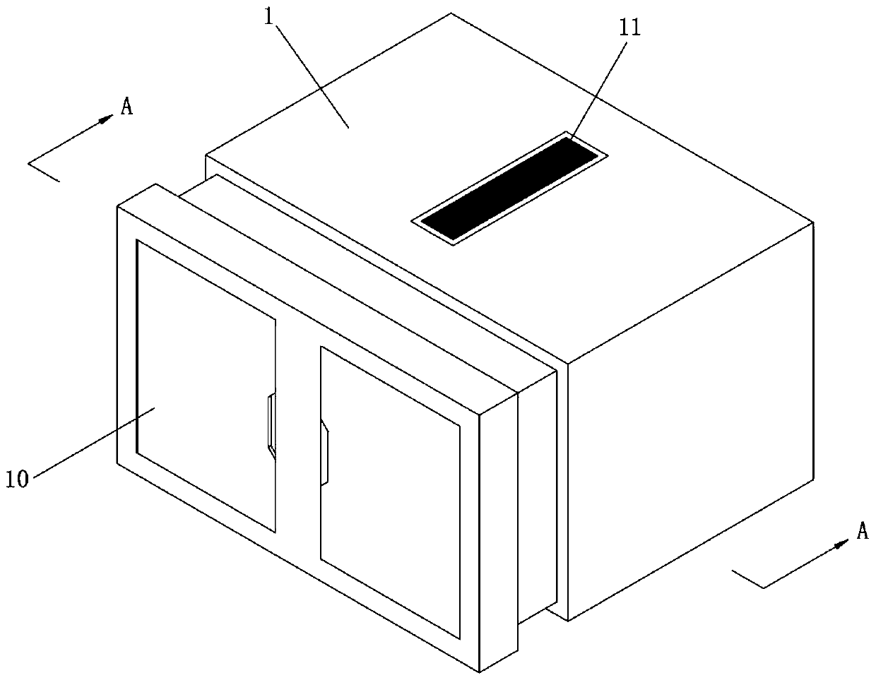
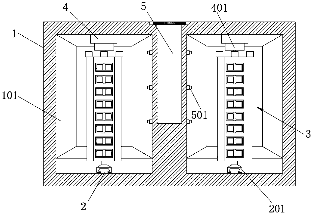
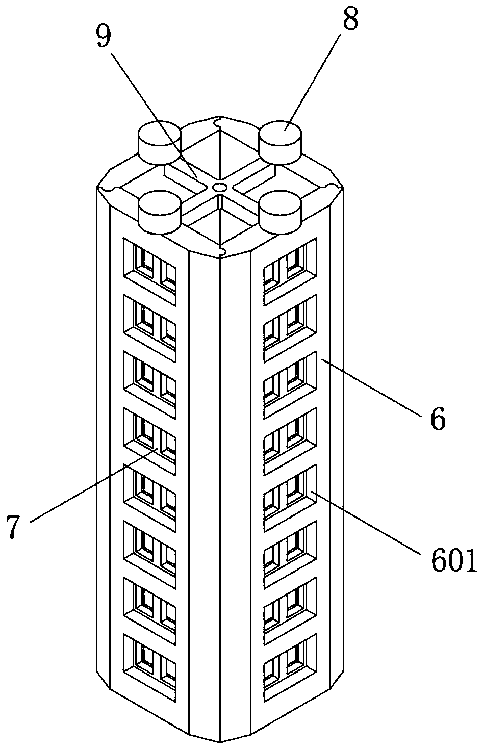
[0021] like Figure 1-4 A kind of magnetron optical coating equipment shown, comprises the coating equipment main body 1 that is cuboid box-shaped structure, is provided with two groups of vacuum chambers 101 that are closed by vacuum sealing door 10 in described coating equipment main body 1, and inside described vacuum chamber 101 A coating system is provided (in practice, the coating system can be any coating equipment, which uses electrons or high-energy lasers to bombard the target, and makes the surface components be sputtered out in the form of atomic groups or ions, and finally deposited on the substrate surface , go through the film forming process, and finally form a thin film; in the target selection, preferably a silicon target, a niobium oxide target and an aluminum target) and a coating support 3 installed in conjunction with the piece to be coated, the bottom of the coating support 3 is supported by a guiding structure, and The top of the coating support 3 is co...

Embodiment 2

[0029] like Figure 1-2A kind of magnetron optical coating equipment shown, comprises the coating equipment main body 1 that is cuboid box-shaped structure, is provided with two groups of vacuum chambers 101 closed by vacuum sealing door 10 in described coating equipment main body 1, and the vacuum chambers of two groups The center of 101 is provided with a group of vacuum pump chambers 5 for the installation of vacuum pump groups. Cooperate with the vacuum pump tube 501 of the pump set.

[0030] Specifically, the vacuum pump set in the vacuum pump chamber 5 includes a plurality of molecular pumps, a set of roughing pumps, a set of Roots pumps and a set of maintenance pumps.

[0031] Specifically, the magnetron optical coating equipment uses molecular pumps, rough pumps, Roots pumps and maintenance pumps to achieve vacuuming of the vacuum chambers 101 on both sides. The pump uses the VSN6501 type roughing pump, the Roots pump uses the NB2400B type Roots pump, and the mainten...


PUM


Abstract

The invention discloses magnetically controlled optical coating equipment. The magnetically controlled optical coating equipment comprises a main coating equipment body of a cuboid box-shaped structure, wherein two sets of vacuum bins closed by vacuum sealing doors are formed in the main coating equipment body, a coating system and a coating support cooperating for the installation of a part to beplated are arranged in each vacuum bin, the bottom of each coating support is supported by a guide structure, and the top of each coating support is connected by a steering structure; each coating support comprises four sets of intercoupling mainboards coupled to each other, and the centers of each four sets of the intercoupling mainboards are connected by an upper set of cross-shaped connectingplates and a lower set of cross-shaped connecting plates; support mounting grooves used for installing rectangular frames are formed in each intercoupling mainboard, and multiple sets of the support mounting grooves are formed in each intercoupling mainboard at equal intervals; and a motor shaft matching groove matched with a motor shaft of a steering motor is formed in the center of the top end of each rectangular frame. The magnetically controlled optical coating equipment is reasonable in structure, easily realizes installation adjustment of electroplated parts, and is high in applicability.

Description

technical field [0001] The invention belongs to the technical field of coating equipment, and in particular relates to a magnetron optical coating equipment. Background technique [0002] Vacuum coating equipment mainly refers to a type of coating that needs to be carried out under a relatively high degree of vacuum, including many types, including vacuum ion evaporation, magnetron sputtering, MBE molecular beam epitaxy, PLD laser sputtering deposition, etc. The main idea is to divide into evaporation and sputtering. Evaporation coating generally heats the target to evaporate the surface components in the form of atomic groups or ions, and settles on the surface of the substrate to form a thin film through scattered points, island structures, vagus structures, and layered growth. For sputtering coatings, it can be simply understood as the use of electrons or high-energy lasers to bombard the target, and the surface components are sputtered out in the form of atomic groups o...

Claims


Application Information

Patent Timeline
Patent Type & Authority Applications(China)
IPC IPC(8): C23C14/35C23C14/50
CPCC23C14/35C23C14/505
Inventor 冯宪轮陈达舜
Owner 湖南华庆科技有限公司
Why Eureka
Try Eureka