
Electric vehicle automatic rapid charging system and charging method

A fast charging, electric vehicle technology, applied in electric vehicle charging technology, electric vehicles, charging stations, etc., can solve the problems of unsafe connectors and inaccurate positioning of charging ports, achieve fast and accurate docking, and improve system reliability. Effect

Pending Publication Date: 2020-02-18
SHANGHAI AOWEI TECH DEV
View PDF7 Cites 2 Cited by
  • Summary
  • Abstract
  • Description
  • Claims
  • Application Information

AI Technical Summary

Problems solved by technology

[0005] The purpose of the present invention is to solve a series of problems such as unsafe high-voltage and high-current connectors in the prior art, inaccurate positioning of the charging port, charging identification, etc., and provide an automatic fast charging system and charging method for electric vehicles

Method used


Image

  • Electric vehicle automatic rapid charging system and charging method

Examples


Embodiment 1

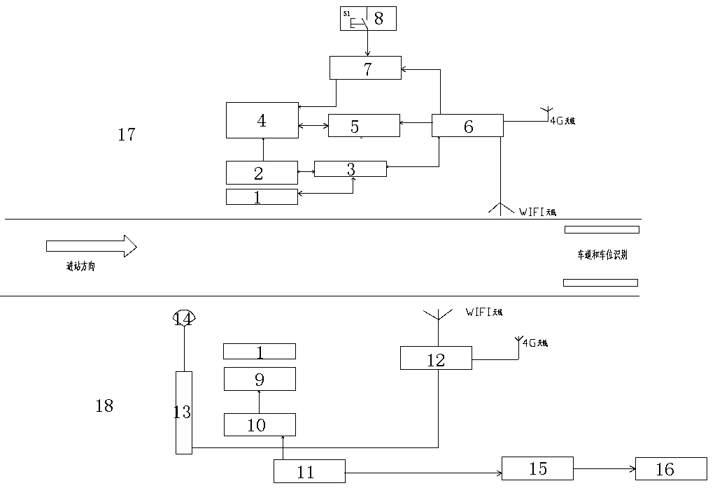
[0030] Embodiment one: see figure 1

[0031] The side part of the car body includes the rolling shutter door set on the car body, the power receiving area, the power receiving guidance control box, the high voltage power distribution cabinet, the super capacitor energy storage unit, the super capacitor management system, the vehicle controller, and the charging start button of the cab. Each device subsystem constitutes the charging and docking system on the vehicle side.

[0032] The side part of the platform is mainly composed of an automatic connection device and a charger. The robot workstation includes a rolling door (for vehicle protection), a charging plug, an automatic connection device, a DC distribution box, a general charging controller, a motion control unit, and a laser radar. Identification system; the part of the charger is composed of the AC power distribution cabinet of the charger.

Embodiment 2

[0033] Embodiment two: working steps are as follows

[0034] Step 1: The electric vehicle stops at the platform under the driving of the driver, and the laser radar captures the position of the label on the side of the vehicle body. The motion control unit transmits the information to the charging master controller, and the charging master controller starts to automatically connect to the hotspot network of the vehicle supercapacitor management system ;

[0035] Step 2: The charging master controller has been connected to the hotspot network of the supercapacitor management system of the electric vehicle. The cab of the electric vehicle shows that a communication connection has been established with the platform charging station. The driver parks the vehicle and the vehicle controller system turns off the driving power of the vehicle. Press the charging button, the whole system enters the charging process;

[0036] Step 3: The supercapacitor management system detects the char...


PUM


Abstract

The invention relates to the technical field of vehicle charging, in particular to an electric vehicle automatic rapid charging system and a charging method. The method comprises the steps that firstly, an electric vehicle is driven by a driver to be stopped at a platform, a laser radar captures the position of a vehicle body side label, a motion control unit transmits the information to a charging main controller, and the charging main controller starts to be automatically connected with a hotspot network of a vehicle super-capacitance management system; and secondly, the charging main controller is connected with the hotspot network of the vehicle super-capacitance management system, a vehicle cab displays communication connection with a platform charging station, the driver stops the vehicle, a vehicle control unit shuts off vehicle driving power, the driver presses a charging button, and the whole system starts a charging process. A charging device adopts an IGBT as a high-voltage-resistant and large-current isolated DCDC scheme of a switch device, a traditional charging module is not used, and the reliability of the system is improved. The charging device is integrated with amonitoring platform, and telemetering and remote control of the system can be achieved.

Description

technical field [0001] The invention relates to the technical field of vehicle charging, in particular to an automatic fast charging system and a charging method for electric vehicles. Background technique [0002] In the field of new energy, new energy vehicles represented by electric vehicles have developed rapidly, but the convenience of charging has always been a major bottleneck restricting the development of electric vehicles. The traditional charging solution is to manually plug and unplug the charging gun to the charging interface of the vehicle, and then the ground charger or on-board charger starts to charge the vehicle. Since the charging voltage is high voltage, manual plugging and unplugging can easily cause high-voltage electric shock accidents, especially Especially in wet weather such as rain and snow, directly plugging and unplugging the high-voltage charging gun poses a greater threat to personal safety. [0003] Traditionally, manually connecting a vehicl...

Claims


Application Information

Patent Timeline
IPC IPC(8): B60L53/31B60L53/68B60L53/35B60L53/66
CPCB60L53/31B60L53/32B60L53/68B60L53/35B60L53/66Y02T90/167Y02T90/16Y02T10/70Y02T10/7072Y02T90/12Y04S30/12
Inventor 翁焕明龚正大解凌峰章锦刘宇梁张文权杨敏
Owner SHANGHAI AOWEI TECH DEV
Learn More